Overcurrent Monitor Operates up to 26V
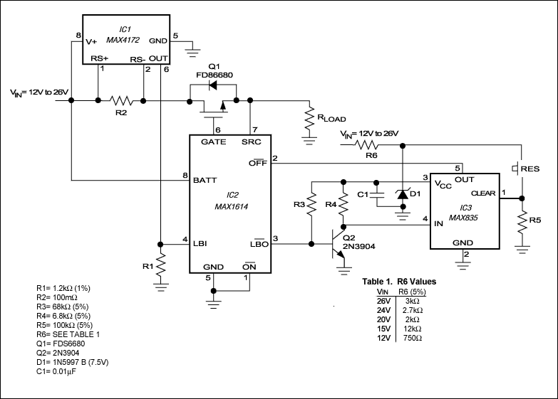
Widespread use of the Universal Serial Bus (USB) has led to a selection of overcurrent-protection circuits for supply rails in the +2.7V to +5.5V range, but few products are available for voltages above that range. The circuit breaker in Figure 1 operates on supply voltages to +26V and trips at a programmed current threshold.

Figure 1. This circuit provides overcurrent protection for supply-rail voltages to +26V.
详情介绍
Widespread use of the Universal Serial Bus (USB) has led to a selection of overcurrent-protection circuits for supply rails in the +2.7V to +5.5V range, but few products are available for voltages above that range. The circuit breaker in Figure 1 operates on supply voltages to +26V and trips at a programmed current threshold.

Figure 1. This circuit provides overcurrent protection for supply-rail voltages to +26V.
IC1 is a high-side current-sense amplifier that monitors supply current via the voltage across R2 and generates a proportional but smaller current at the OUT terminal:
IOUT = (R2 ITRIP)/100.
R1 and R2 determine the trip current:
R1 = 120/(R2 ? ITRIP).
R1 in the figure was chosen for a trip current of 1A, but values to 10A are acceptable. Supply current at the trip level produces a voltage across R1 that triggers the "low-battery" comparator in IC2 (a high-side, N-channel MOSFET driver). The comparator output (LBO) turns on Q2 to saturation, causing the latched output of IC3 (a micropower voltage monitor) to go low. Applied to IC2's pin 2, this signal disconnects the power by turning off Q1.
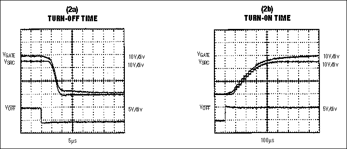
Power remains off until IC3 is unlatched (by depressing the reset button). (You may also need to push the button following initial power-up, to ensure the correct circuit state at that time.) Choose R6 according to Table 1 (in Figure 1) for supply voltages of +12V and above. For supply voltages below +12V, D1 and R6 are not required. The signal delay from IC3 to the load (via IC2 and Q1) is as follows: turn-off time is about 5µs (Figure 2a), and turn-on time is about 400µs (Figure 2b).

Figure 2. With Figure 1's load-current trip threshold set at 1A, the load voltage (middle waveform) turns off (a) and on (b), as shown. (VOFF is the signal at IC2, pin 2.)
A similar idea appeared in the 9/11/98 issue of EDN.
