DVB-T Receiver Reference Design with the MAX3580
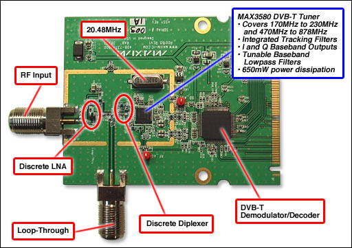
Figure 1. DVB-T receiver reference design features the MAX3580.
Figure 2. System block diagram.
详情介绍
Figure 1. DVB-T receiver reference design features the MAX3580.
Figure 2. System block diagram.
Lab Measurements
Figure 3. VHF sensitivity measures better than -97dBm for QPSK modulation with Code Rate 1/2.
Figure 4. UHF sensitivity measures better than -96dBm for QPSK modulation and Code Rate 1/2.
Figure 5. The adjacent channel selectivity (ACS) is better than 32dBc for N ±1 digital adjacents and better than 38.5dBc for N ±1 analog adjacents. These measurements show MBRAI compliance for category a/b1 requirements.
Loop-Through Performance
| Parameter | Conditions | Measured | Units | ||
|---|---|---|---|---|---|
| Min. | Typ. | Max. | |||
| Frequency Range | 47 | 862 | MHz | ||
| Return Loss at Loop-Through Out | Antenna input terminated with 75Ω | 10 | dB | ||
| Power Gain to Loop-Through Out | -1.2 | 2.7 | dB | ||
| Noise Figure to Loop-Through Out | 4.5 | 5.0 | dB | ||
| Loop-Through Out to RF In Isolation | 31 | dB | |||
| Loop-Through Out to Tuner In Isolation | 15 | dB | |||
DVB-T Terrestrial Frequency Plan in Europe
Figure 6. The DVB-T/PAL signal is broadcast in the VHF Low, VHF High, and UHF bands as shown above. Channel spacing is 7MHz in the VHF band and 8MHz in the UHF band.
Detailed Description
The MAX3580 fully integrated, direct-conversion TV tuner is designed for digital video broadcasting-terrestrial (DVB-T) applications. The integrated tuner covers a 170MHz to 230MHz input frequency range for the VHF-III band and 470MHz to 878MHz for the UHF band.
The MAX3580 integrates an RF input switch and a multiband tracking filter, allowing low-power tuner-on-board applications without the cost and power-dissipation issues of dual-conversion tuner solutions. The zero-IF architecture eliminates the need for SAW filters by providing baseband I and Q outputs directly to the demodulator. In addition, DC-offset cancellation is implemented on-chip using a mixed-signal architecture to improve the second-order distortion performance and the dynamic range of the downstream digitizer and demodulator.
The MAX3580 communicates using a 2-wire serial bus. The device typically operates from a +3.3V power supply, dissipating 650mV. The MAX3580 is available in a small 32-pin thin QFN package (5mm x 5mm) with an exposed paddle. Electrical performance is guaranteed over extended -40°C to +85°C temperature range.
References
IEC62002-IEN
NorDig-Unified ver 1.0.3
Application note 3700, "Front-End Diplex Filter for MAX3580"
Application note 4258, "Application Considerations for the MAX3580 DVB-T Tuner"