MONTEREY (MAXREFDES15#):超低功耗、高精度、4–20mA、2线电流环路传感器
概述
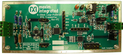 高清图片 (JPG) |
4–20mA电流环路广泛用作工业应用中的模拟通信接口,通过双绞线电缆将远端传感器的数据发送至中央控制中心的可编程逻辑控制器(PLC)。设计中,4mA表示最低温度值,20mA表示最高测量温度。电流环路的主要优势有四方面:首先,信号准确度不受环路中压降的影响,只要电源电压高于环路的总压降即可;第二,使用两根线作为电源以及整个环路的数据通信;第三,抗噪性更好;最后,成本低、安装简单。
Monterey设计基于完备的Maxim方案,兼具超低功耗、高准确度及高精度。
- MAX44248 低噪声、零漂移运算放大器
- MAX11200 高准确度、低功耗、24位Δ-Σ ADC
- MAXQ615 低功耗微控制器
- MAX5216 低噪声、高精度、低功耗16位DAC
- MAX9620 低功耗运算放大器
- MAX15007 宽输入电压范围、低功耗LDO
环路供电传感器发送器的目标应用为工业传感器、工业自动化以及过程控制,但也可用于要求高精度转换的任意应用。
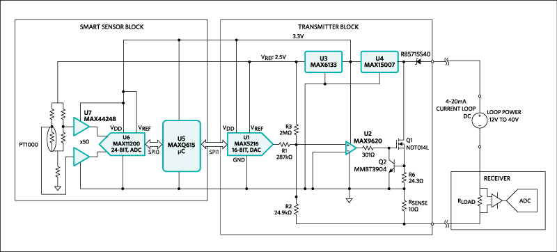
简单、可靠、良好抗噪性、长距离以及低成本等特性使Monterey (MAXREFDES15#) (图1)接口非常适合于工业过程控制和远端物体自动化。
高清图片 (GIF)
图1. Monterey子系统设计方框图
特性
- 超低功耗
- -100°C至+100°C区间
- 高准确度
- 高精度
- 电源简单、输入范围宽
- 系统电流消耗小于2.1mA
- 电阻温度检测器(RTD) PT1000
- 分辨率为10,000个字或0.1%
- 精度为0.25%
所需设备
- 10V至40V电源
- 高精度电流表
- RTD PT1000传感器或温度校准器
快速入门
- C将工业标准电源连接在J1的LOOP+和LOOP-端,为电路板供电。
- 将传感器连接至J3。电路板的目前设计配置为2线RTD应用。对传感器侧稍加修改,即可用于3/4线RTD应用。
详情介绍
Introduction
 More detailed image (JPG) |
The 4–20mA current loop is widely used as an analog communication interface in industrial applications for transmitting the data from remote sensors to a programmable logic controller(PLC) in a central control center over a twisted pair cable. Here, 4mA represents the lowest temperature value, and 20mA represents the highest measured temperature. There are four main advantages of the current loop. First, the accuracy of the signal is not affected by the voltage drop in the loop, as long as the power-supply voltage is greater than the total voltage drop across the loop. Secondly, it uses two wires for power as well as data communication over the entire loop. Thirdly, it is more immune to noise. And lastly, it is offered at a low cost and easy installation.
The Monterey design is based on a complete Maxim solution which combines ultra-low power, high accuracy, and high precision.
- MAX44248 low-noise,. zero-drift op amplifier
- MAX11200 high-accuracy, low-power, 24-bit delta-sigma ADC
- MAXQ615 low-power microcontroller
- MAX5216 low-noise, high-accuracy, low-power 16-bit DAC
- MAX9620 low-power op amplifier
- MAX15007, wide Input voltage low-power LDO
This loop-powered sensor transmitter is targeted for industrial sensors, industrial automation, and process control, but it can be used in any application requiring high-accuracy conversion.
Simplicity, reliability, good noise immunity, long distance, and low cost make the Monterey (MAXREFDES15#) (Figure 1) interface well suited for industrial process control and automation of remote objects.

More detailed image (GIF)
Figure 1. The Monterey subsystem design block diagram.
Features
- Ultra-low power
- -100°C to +100°C interval
- High accuracy
- High precision
- Simple power supply and wide input range
- System current consumption less than 2.1mA
- Resistance temperature detector (RTD) PT1000
- Resolution 10,000 counts or 0.1%
- Accuracy 0.25%
Equipment Required
- 10V to 40V power supply
- High-accuracy current meter
- RTD PT1000 sensor or a temperature calibrator
Quick Start
- Connect an industrial standard power supply across LOOP+ and LOOP- terminals of J1 to power up the board.
- Connect the sensor across J3. The current design of the board is configured for 2-wire RTD application. Minor modifications at the sensor side can be performed to use a 3/4-wire RTD application.
Jumper Descriptions
| Table 1. Connector Description and Default Jumper Positions | ||
| Jumper | Default Position | Function |
|---|---|---|
| J1 | Installed | Power pin for Monterey Board. Connect across LOOP+ and LOOP- for power. |
| J2 | Installed | |
| J3 | Installed | Connect RTD across IN+ and IN-. |
| J4 | Installed across pins 1 and 2 | Using a jumper across pins 1 and 2 of J4 uses the MAX44248. This case is used to gain the input signal. |
| J5 | Not installed | Using a jumper across pins 2 and 3 of J5 bypass the MAX44248. The input signal range is high and amplifier is not required. |
| J6 | Not installed | |
| J7 | Installed | |
| J8 | Installed | |
| J9 | Installed | When not installed, this jumper’s subsequent pins can be used to measure the loop-generated current. |
Test Procedure
Relation Between Current Output (mA) and Temperature (°C)
The simplified correspondence between the generated output current and the temperature can be expressed by the following equation below:
IOUT = 16mA[T°C/200°C] + 12mA
where T is the temperature sensed by the RTD and IOUT is the current loop.
If RTD Used
- If RTD is used, test it at different temperatures, and observe the associated loop current.
- At -100°C, the expected current is 4mA
- At -50°C, the expected current is 8mA
- At 0°C, the expected current is 12mA
- At +50°C, the expected current is 16mA
- At +100°C, the expected current is 20mA
If RTD Calibrator Used
- If calibrator is used, test by varying the temperature value to change the resistance across the RTD calibrator terminals.
- Observe:
- At -100°C, the expected current is 4mA
- At -50°C, the expected current is 8mA
- At 0°C, the expected current is 12mA
- At +50°C, the expected current is 16mA
- At +100°C the expected current is 20mA
Detailed Description
The entire 4–20mA loop application consists of:
- Smart sensor transmitter (process measurement field instrument)
- Receiver (PLC)
The MAXREFDES15# contains the sensor analog front-end, the microcontroller, and the transmitter (Figure 2). The 4–20mA receiver can be implemented by Santa Fe (MAXREFDES5#) and Campbell (MAXREFDES4#). Information about the Santa Fe and Campbell can be found at
Santa Fe (MAXREFDES5#)
Campbell (MAXREFDES4#)
This document describes the operation of the smart sensor enabling the 4–20mA loop process.
The Smart Sensor Transmitter
The smart sensor transmitter block (see Figure 2) consists of:
- Analog front-end
- Microcontroller
- Transmitter
The analog front-end combines the following:
- RTD sensor PT1000
- Ultra-precision, low-noise, zero-drift operational amplifier (MAX44248)
- Ultra-low-power, high-accuracy delta-sigma ADC (MAX11200)
The low-power microcontroller (MAXQ615) is used to implement calibration and linearization.
The sensor used in the Monterey board is a platinum resistance thermometer (PT1000). The entire system offers excellent accuracy of wide temperature range from -100°C to +100°C. The basic operation of this sensor block is to measure the temperature, which is subsequently converted into current by the 4–20mA loop current source.
The variation in temperature creates a change in galvanic resistance of the wheatstone bridge, due to change in the resistivity of the RTD element. As the temperature ranges from -100°C to +100°C, a 150mV differential voltage swing is observed across the wheatstone bridge to INPUT A and INPUT B of the 50x amplifier.
The gain stage is used to amplify very minor differential voltage arising from the wheat-stone bridge. Jumpers J4 and J5 provide options to use the amplifier stage or bypass it. When used, the differential voltage is gained 50 times by using the MAX44248 before digitized by the MAX11200 ADC. A dual amplifier stage (MAX44248) is used as a 50x differential amplifier. The gain can be changed by changing the resistors to match the desired signal range from the wheatstone bridge, thereby maintaining proper input signal range and output swing from the amplifier driving the ADC.
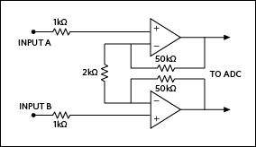
Figure 2. Amplifier gain stage sensor block.
The MAXQ615 microcontroller then maps for the voltage represented to the calibrated temperature reading that the PT1000 is expected to show. The MAXQ615 has a transfer function that compensates for the nonlinear function of the PT1000. The below equation represents the compensation function:
T = 0.8462dV2 - 48.6623dV - 0.1519
where T is the temperature and dV is differential voltage
The above information only supports the PT1000 and for this specified wheatstone bridge configuration, sensor front-end component selection. This mapped information is then sent to the transmitter through the SPI interface for loop-current generation.
The Transmitter Block
The transmitter block description and step-by-step design guide is discussed in the MAX5216LPT data sheet.
Evaluation of 4–20mA Loop Application
To evaluate the complete 4–20mA loop application, the following is required.
- The Monterey Board (MAXREFDES15#), consisting of the smart sensor block and low-power transmitter
- An analog front-end receiver (Santa Fe, Campbell, Fresno)
- An interface board such as Munich USB2PMB1# can be used to facilitate the evaluation of this application.
The following step-by-step user guide explains testing the entire application using the
- RTD Fluke 724 calibrator at the sensor end
- Monterey Board MAXREFDES15#
- Santa Fe Board MAXREFDES5# AFE as receiver
- Munich USB2PMB1# adaptor board
- Download the most recent version of the Munich USB2PMB1# board software, PMOD_SPI.ZIP. Save the software to a temporary folder and decompress the ZIP file.
- Connect the USB cable between the Munich USB2PMB1# board and the PC; the USB driver is installed automatically.
- Connect the Munich USB2PMB1# board’s 2 x 6-pin right-angle connector to the Santa Fe's 2 x 6-pin right-angle header.
- With the power supply off, connect the positive lead of 12V DC power supply to LOOP+ on the Monterey board.
- Connect LOOP- on the Monterey board to AIN2 on the Santa Fe board.
- Connect GND2 on the Santa Fe board to the negative lead of the power supply.
- Connect RTD connector of the Fluke 724 to IN+ of the Monterey board.
- Connect COM connector of the Fluke 724 to IN- of the Monterey board.
- Push the RTD button on the Fluke 724 to select PT1000.
- Turn on the power supply.
- Open the Munich USB2PMB1# GUI and select the Santa Fe tab.
- Click on the Scan_Devices tab and make sure that Hardware: Santa Fe Connected is shown on the GUI.
- Select 0V to +6V input range on the GUI.
- Select PlotCurrent on the GUI.
- Push the Measure/Source button on the Fluke 724 to select Source.
- Adjust the arrow button on the Fluke 724 to set the temperature to -100°C. Observe that the current display on the GUI is 4mA.
- Similarly, adjust the arrow button on the Fluke 724 to set the temperature to +100°C. Observe that the current display on the GUI is 20mA.
Lab Measurements
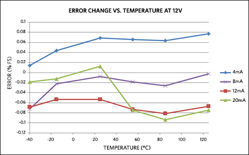
Figure 3. Error change vs. temperature at 12V.
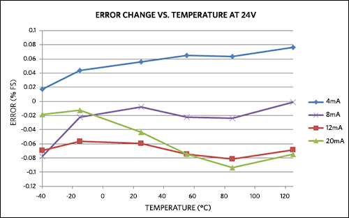
Figure 4. Error change vs. temperature at 24V.
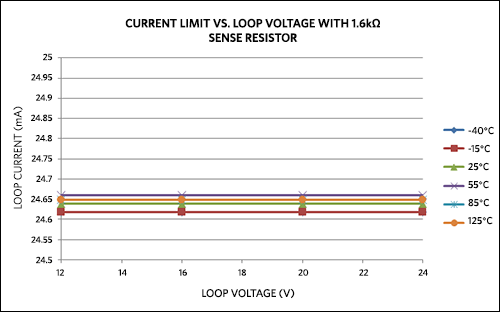
Figure 5. Current limit vs. loop voltage with 1.6kΩ sense resistor.
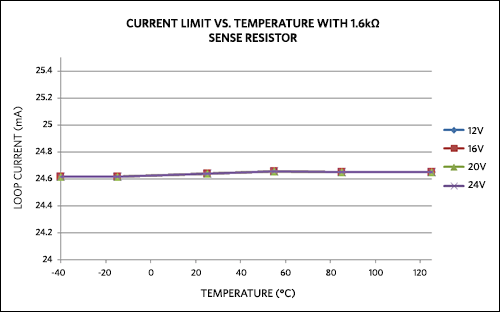
Figure 6. Current limit vs. temperature with 1.6kΩ sense resistor.
