High-Performance Temperature Measurement Using Thermocouples and Precision Delta-Sigma ADCs, Part 2
Introduction
This two-part series presents the design of a cost-effective, portable, high-resolution data-acquisition system (DAS) based on a precision delta-sigma analog-to-digital converter (ADC). The Part 1 article reviewed the history of thermocouple technology and the principal of the operation. It described a thermocouple interface with the MAX11200 ADC evaluation (EV) kit.1
This Part 2 of the series presents a dedicated reference design (RD) in which the MAX11200 ADC interfaces with a thermocouple and platinum resistance temperature detector (PRTD) using a simple multiplexor. No additional instrumentation amplifiers, low-noise references, and optical isolation are needed for precise temperature measurement. The new RD is cost effective, compact, and low power. We also describe the high-resolution thermocouple’s DAS and the software required to achieve accuracies of ±1°C, or better, using standardized linearization calculation algorithms.
详情介绍
A similar version of this article appears on EDN, October 18, 2013.
Introduction
This two-part series presents the design of a cost-effective, portable, high-resolution data-acquisition system (DAS) based on a precision delta-sigma analog-to-digital converter (ADC). The Part 1 article reviewed the history of thermocouple technology and the principal of the operation. It described a thermocouple interface with the MAX11200 ADC evaluation (EV) kit.1
This Part 2 of the series presents a dedicated reference design (RD) in which the MAX11200 ADC interfaces with a thermocouple and platinum resistance temperature detector (PRTD) using a simple multiplexor. No additional instrumentation amplifiers, low-noise references, and optical isolation are needed for precise temperature measurement. The new RD is cost effective, compact, and low power. We also describe the high-resolution thermocouple’s DAS and the software required to achieve accuracies of ±1°C, or better, using standardized linearization calculation algorithms.
Thermocouple Calculation Overview
In Part 1 of this series2 we explained that thermocouples generate a voltage/charge (VOUT) and do not require any voltage or current excitation. Readers familiar with the technology can jump to the next section.
VOUT is the function of the temperature differential, - (TJUNC - TCOLD), produced by two dissimilar metals. The differential is due to the different electric potentials for the Metal 1 and Metal 2 and the temperature gradient applied to them.3 The NIST ITS-90 Thermocouple Database4 defines this VOUT function for most practical Metal 1 and Metal 2 combinations and enables the calculation of relative temperature TJUNC based on the VOUT measurements. It is important to emphasize that TJUNC is only a relative temperature in relation to the cold junction (TCOLD). To find the absolute temperature (in °C, °F, or K), TCOLD temperature must be independently measured:
| Tabs = TJUNC + TCOLD | (Eq. 1) |
where:
Tabs is the absolute temperature of the hot junction;
TJUNC is the relative temperature of the hot junction versus the cold reference junction;
TCOLD is the absolute temperature of the reference cold junction.
Note that the TJUNC and TCOLD temperature measurements must be produced in the same units (i.e., in °C, °F, or K).
Equation 1 dictates that the thermocouple measurement requires VOUT precision measurements for the hot junction, as well as an accurate complimentary sensor5 for the cold-junction temperature measurements.
Accuracy and Resolution
Thermocouple temperature calculation can be done using simplified linearization algorithms. The approximate absolute temperature is calculated as:
| Tabs = (E + Ecj)/k | (Eq. 2) |
where:
E is the measured thermocouple output in mV;
Tabs are the absolute temperature of the thermocouples in °C;
Ecj is the cold-junction thermocouple equivalent output in mV, calculated by using the cold junction temperature, measured independently, and the ITS-90 Thermocouple Database tables;
k is the thermocouple average sensitivity.
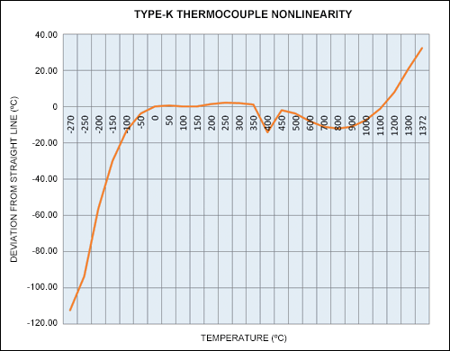
While a linearization approach could substantially reduce the calculation volume and complexity, it can also produce large temperature-measurement errors. For example, in a K-type thermocouple linear approximation by Equation 2 allows only a 1°C to 4°C degree of precision in the narrower -50°C to +350°C temperature range. At +1000°C the calculation errors could reach around 7°C, while at -100°C the error would be around 13°C. (See Table 2.) The root cause of the large errors can be traced to nonlinearity, as shown in Figure 1.

Figure 1. K-type thermocouple nonlinearity. The data show the output voltage vs. temperature for a K-type thermocouple. The curve is reasonably linear in the range of -50°C to +350°C, and it clearly has significant deviations from absolute linearity at the “ends,” below -50°C and above +350°C.6
Output voltages from the most common thermocouples,7, 8 as a function of temperature, are highly nonlinear. This nonlinearity can produce large errors in the extended temperature ranges as shown in the K-type thermocouple example in Figure 1.
Errors in the extended temperature ranges are also common for application-specific ICs (ASICs) like the MAX31855 thermocouple-to-digital converter. For example, if an extended -270°C to +1372°C temperature range is needed for K-type thermocouples, then the MAX31855 thermocouple’s overall accuracy will be ±6°C. A similar situation exists for other popular thermocouples.
Consequently, Figure 1 and Equation 2 demonstrate that rather complex nonlinear compensation is needed to further improve the accuracy of a popular industrial thermocouple.
Improving the Accuracy
We return now to the NIST ITS-90 database cited above. Substantial accuracy improvement (in the order of magnitude versus linearization algorithms) can be achieved with the modern NIST ITS-90 Thermocouple Database, which allows the polynomial equation to be used to convert thermocouple voltage to temperature (°C) over a wide temperature range using standardized polynomial coefficients.9 New contemporary NIST ITS-90 coefficients are provided for the temperature intervals (versus single intervals in the previous standards), and they allow temperatures to be calculated with good accuracy (around ±0.1°C)—more than sufficient for most industrial applications.
Improving Resolution
The MAX11200 used in this RD is a low-power, 24-bit, delta-sigma ADC. It has an extremely low input-referred RMS noise of 570nV at 10sps. The noise-free resolution (NFR) is around 6.6 × RMS noise and represents a value of 3.762µV. (This is called flicker-free code.) The NFR represents the minimum values that can be reliably differentiated by the ADC in voltage in the measurement range.
Table 1 provides more precise NFR resolution values than in Part 1 of this series10 where the assumption was that NFR = VREF/220. Therefore, a detailed calculation for a 0°C to 500°C range is:
Noise free codes = 20.644mV/3.762µV P-P
Noise free codes = 5487.5 codes
Temp (resolution) = 500°C/5487.5
Temp (resolution) = 0.0911°C
Table 1 provides the calculated values of °C/NFR error for three temperature ranges. For all the temperature ranges the NFR values are below 0.15°C, which is better than for ASICs and more than sufficient for most thermocouples in industrial and medical applications.
| Table 1. °C/NFR Error for Defined Temp Ranges | |||
| Temperature Range (°C) | -200 to 0 | 0 to 500 | 500 to 1372 |
|---|---|---|---|
| Voltage Range (VINT, mV) | -5.891 | 20.644 | 34.242 |
| Resolution (°C/NFR) | -0.1277 | 0.0911 | 0.0871 |
Electronic Design
Interfacing a Thermocouple with the MAX11200-based DAS Board
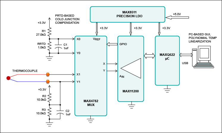
Part 1 of this article described the thermocouple interface with the MAX11200 EV kit. That design produces very good results, but includes many components, optical isolation, and features intended for general applications. Figure 2 shows a simplified schematic for the MAX11200-based DAS board, here optimized for cost-effective portable thermocouple measurements applications. Included on board is the PRTD.11
High resolution is achieved by using the MAX11200 fully differential capability. A ratiometric approach utilizes the ADC’s excellent common-mode rejection (100dB or better) and, therefore, allows the design to achieve a desirable signal-to-noise ratio (SNR) without optical isolation and dedicated reference.

Figure 2. Block diagram of the MAX11200 DAS-based temperature measurement system. Design allows dynamic measurement of either the thermocouple or PRTD.
In Figure 2 the MAX11200’s GPIO is set to control the precision multiplexer, the MAX4782, which selects either the thermocouple or the PRTD. This approach allows dynamic measurement of either the thermocouple or PRTD using a single MAX11200; it improves system precision and reduces the requirements for calibration. The PRTD is a PT1000 (PTS 1206, 1000Ω) used for temperature measurement of the cold junction. The MAX8511 precision LDO powers the system and provides a reference voltage for the MAX11200.
The Algorithms
The algorithms selected for this design are similar to those presented in Part 1 of this article and can be used for any type of the thermocouple. The NIST ITS-90 provides different sets of the coefficients for specific temperature intervals: -200°C to 0°C, 0°C to +500°C, and +500°C to +1372°CK-type thermocouples. Each temperature interval must be preselected for use in Equation 3.
| T = d0 + d1 × E1 + d2 × E2 + ... dN × EN | (Eq. 3) |
where:
T is the temperature in °C;
E is the VOUT thermocouple output in mV;
dN is the polynomial coefficients unique to each thermocouple;
N is the maximum order of the polynomial.
The simplified linearization algorithm in equation 3 allows the designer to select temperature intervals based on Table 1 with sufficient accuracy.
Processing the Data
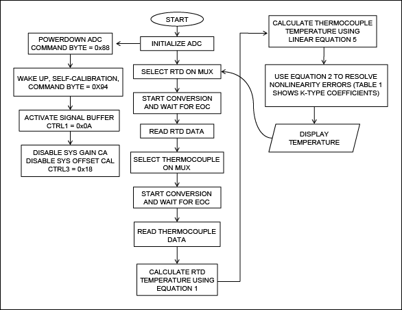
The firmware in the MAXQ622 microcontroller (Figure 2) provides data-reading capability to the software through USB. The software implements algorithms based on Equations 2 and 3. Raw measurement data is processed inside the PC. The software manages the following major functions which are charted in Figure 3:
- Initializes the MAX11200 ADC
- Collects and processes the ADC's output data
- Calculates the temperature using Equations 2 and 3
During initialization, the MAX11200 ADC goes through the self-calibration process, enables the input signal buffers, and disables both system gain calibration and system offset calibration. This DAS allows reasonably fast data acquisition with excellent (100dB or better) normal-mode powerline 50Hz/60Hz rejection. Selection of the sample rates is very important for reducing noise and interference in the industrial measurements.
The recommended external clock for 60Hz line-frequency rejection is 2.4576MHz, which is effective for data rates of 1, 2, 5, 10, and 15sps. For 50Hz line-frequency rejection, the recommended external clock is 2.048MHz, which is effective for data rates of 0.83, 2.08, 4.17, 8.33, and 12.5sps.
Input signal buffers increase the input impedance to the high megohms range. This improves measurement precision because it practically eliminates the shunting effect of the input dynamic current.

Figure 3. Chart outlines the top-level actions of the DAS firmware and software.
Design Implementation
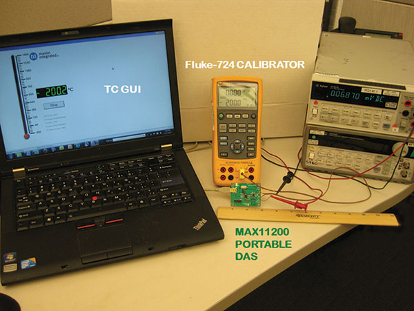
Figure 4 shows the implementation of the cost-effective, compact high-resolution DAS shown in Figure 2. The DAS was designed and tested with the popular K-type OMEGA® thermocouple KTSS-11612 and verified with the Fluke® 724 temperature calibrator. The DAS board dimensions are only 2in × 1.5in and overall Bill of the Materials cost is below $10 (U.S.), depending on the quantity. The current design is powered through a laptop USB port. The battery-based power consumption could be reduced to below around 3mA by reducing the clock frequency and removing the status LEDs.

Figure 4. The setup for the temperature measurement system featuring the MAX11200 ADC.
A Fluke 724 temperature calibrator supplies precision voltage that corresponds to the K-type thermocouple’s output in the -200°C to +1300°C range to the MAX4782 X1 and Y1 inputs. An on-board PT1000-based circuit connected to the MAX4782 X0 and Y0 inputs provides the cold junction compensation module.
The software collects and processes data generated by thermocouple and PT1000 outputs. The MAX11200’s GPIOs allow dynamic control of the MAX4782 for selecting either the thermocouple or the PRTD. The MAXQ622 microcontroller manages the MAX11200 measurement and transmits data though a USB port to the laptop computer.
The laptop display (Figure 3) shows a traditional analog thermometer with full-scale approximate measurements, as well as a precise digital thermometer reflecting final temperature calculations (in °C or °F).
Table 2 lists measurements and calculations using Equations 2 and 3 for the -200°C to +1300°C temperature range.
| Table 2. Measurements for the -200°C to +1300°C Temperature Range | |||
| Temperature—Fluke 724 (°C) | Temperature—Thermocouple GUI (°C) | Temperature Error vs. Calibrator (°C) | Temperature Calculated by Linear Equation (°C) |
|---|---|---|---|
| -200 | -200.2 | -0.2 | -143.6 |
| -100 | -100.4 | -0.4 | -86.62 |
| -50 | -50.4 | -0.4 | -46.01 |
| 0 | -0.3 | -0.3 | 0.05 |
| 20 | 19.7 | -0.3 | 19.68 |
| 100 | 99.7 | -0.3 | 99.96 |
| 200 | 199.8 | -0.2 | 198.69 |
| 500 | 499.9 | -0.1 | 503.7 |
| 1000 | 1000.4 | 0.4 | 1006.92 |
| 1300 | 1300.9 | 0.9 | 1278.4 |
Table 2 shows that with use of Equation 2, the MAX11200-based DAS achieves precise temperature measurement in the order of ±0.5°C over a very wide temperature range with about 0.9°C accuracy at +1300°C. Linear approximation by Equation 2 allows the selection of temperature intervals quickly and efficiently. Using Equation 2 required relatively complex calculations with polynomial calculation algorithms. Modern processors like MAXQ622, in conjunction with portable personal computers, process complex calculations efficiently and in a cost-effective manner.
Detailed schematics, a bill of materials (BOM), and application software for this design are available to all qualified customers .
Conclusion
In recent years we have seen the development of cost-effective, thermocouple-based temperature-sensing measurement across very wide temperature ranges. In fact, a range of -270°C to +1750°C is quite doable at a reasonable cost and often with very low power consumption.
In this RD, the MAX11200 low-power ADC interfaces with a thermocouple and PRTD using a simple multiplexor. No additional instrumentation amplifiers, low noise references, and optical isolation are needed. Using a microcontroller and standard personal computer, the MAX11200-based DAS achieves precision on the order of ±0.5° from -200°C to +1000°C. This temperature-measurement RD offers high performance, yet it is compact and cost effective. It is ideal for portable sensing applications and compares favorably with more precise, but more expensive and complex designs discussed in the Part 1 article.
References
- Mirza, Sohail, Shtargot, Joseph , “Modern thermocouples and a high-resolution delta-sigma ADC enable high-precision temperature measurement”, EE Times, 6/22/2011, and Reference Schematic 5032
- Ibid.
- Using Thermocouples, Thermocouple Introduction and Theory (PDF),
- See the NIST online databases
- For more details about high-accuracy temperature measurements using a PRTD, see Maxim Integrated application note 5244, “Modern PRTD Temperature Sensors and High-Accuracy Delta-Sigma ADCs Enable Wide Range High-accuracy Temperature Measurements”. Equation 4 from this application note is used for RTD temperature measurement.
- Ibid.
- NIST online databases, op. cit.
- For more information see Maxim Integrated application note 4679, “Thermal Management Handbook”.
- NIST online databases, op. cit.
- See reference 1.
- For more details of high-accuracy temperature measurements using PRTD, see the application note cited in reference 8.
- For information on the K-type OMEGA thermocouple KTSS-116 (PDF), go to “Molded Transition Joint Probes,” OMEGA.
