MAXREFDES27#:IO-LINK接近检测光传感器

概述
当今工厂对自动化的依赖程度越来越高,对人工劳力的依赖越来越小。随着机器人使用的日益普及,对接近检测的需求越来越旺盛。接近检测传感器能够检测达到基准点位置一定距离范围内的物体。当目标物体通过预定义的距离门限时,器件可翻转,从而用作开关;当物体在传感器的范围内移动时,器件也可提供连续读数。现在有多种类型的接近检测传感器,例如光、电感、电容、超声、磁甚至机械式传感器。有些应用的要求比较特殊,使得某种类型的传感器可能比其它类型更合适。得益于光电技术的快速发展,光传感器具有极大的通用性。这种通用性使其能够满足大量的工业接近检测需求1,包括检测磁性或非磁性物体、极小的物体、超长距离以及快速响应时间。
工厂也倾向于使用广泛接受的工业协议。IO-Link是第一种开放式、现场总线不可知、低成本、点对点串行通信总线协议,用于与传感器及执行器通信,已经被采纳为国际标准(IEC 61131-9)2。IO-Link最终标准化了全世界工业设备的互操作性。IO-Link可直接由PLC操作,也可集成到任何标准现场总线,使其快速成为与MAXREFDES27#等智能设备通信的事实标准。既简单又智能的IO-Link支持工业上最小的低成本智能传感器。
MAXREFDES27#为微小的IO-Link接近检测传感器,带有红外接收器、配套IR LED驱动器、IO-Link收发器以及高效的降压转换器,全部安装在8.2mm x 31.5mm印刷电路(PC)板上。Maxim Integrated和Technologie Management Gruppe Technologie und Engineering (TMG TE)通力协作,将MAXREFDES27#设计为兼容第1.1/1.0版IO-Link协议的接近检测传感器参考设计。MAXREFDES27#设计包括行业标准的Maxim Integrated IO-Link设备收发器(MAX14821);微小低压差线性稳压器(MAX8532);高效率、高电压、降压型转换器(MAX17552);使用TMG TE的IO-Link设备栈的Renesas超低功耗、16位微控制器(RL78),Maxim Integrated接近检测传感器(MAX44000)。图1所示为系统方框图。
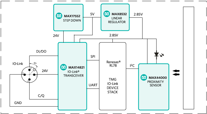
图1. MAXREFDES27#参考设计方框图。
详情介绍
 放大+
放大+
Introduction
Today's factories rely more on automation and less on manual labor. With this increased use of robotics comes the increased need for proximity sensing. Proximity sensors are devices that can sense when an object is a specific distance away from a reference point location. They are able to act as a switch by flipping when the target object passes a predefined distance threshold. They can also provide continuous readings when objects are changing distances within a sensor's range. Several types of proximity sensors exist today such as optical, inductive, capacitive, ultrasonic, magnetic, and even mechanical. Some applications have special requirements that may make one type better suited than another. Optical sensors are extremely versatile, due to the rapid development of photoelectric technology. This versatility allows them to solve the bulk of the industrial proximity sensing needs1. Such needs include sensing of metallic or non-metallic objects, very small objects, over long distances, and with fast response times.
Factories are also moving towards using universally accepted industrial protocols. IO-Link is the first open, field bus agnostic, low-cost, point-to-point serial communication protocol used for communicating with sensors and actuators that has been adopted as an international standard (IEC 61131-9)2. IO-Link finally standardizes interoperability of industrial equipment from all over the world. IO-Link can function directly from the PLC or can be integrated into all standard field buses, quickly making it the defacto standard for universally communicating with smart devices like the MAXREFDES27#. IO-Link, being simple yet intelligent, allows for the smallest low-cost smart sensors in the industry.
The MAXREFDES27# is a tiny IO-Link proximity sensor with an IR receiver, matching IR LED driver, IO-Link transceiver, and energy-efficient step-down converter all on an 8.2mm x 31.5mm printed circuit (PC) board. Maxim Integrated and Technologie Management Gruppe Technologie und Engineering (TMG TE) collaborated in designing the MAXREFDES27# as an IO-Link version 1.1/1.0 compliant proximity sensor reference design. The MAXREFDES27# design consists of an industry standard Maxim Integrated IO-Link device transceiver (MAX14821), a tiny low-dropout linear regulator (MAX8532), an efficient high-voltage step-down converter (MAX17552), a Renesas ultra-low-power 16-bit microcontroller (RL78) utilizing TMG TE's IO-Link device stack, and a Maxim Integrated proximity sensor (MAX44000). Figure 1 shows the system block diagram.
Figure 1. The MAXREFDES27# reference design block diagram.
Features
- Tiny industrial sensor form factor
- Ultra low power: 150mW
- Low cost
- IEC 61131-9
- IO-Link version 1.1 and 1.0 compliant
- Field bus agnostic
- Transient voltage suppression
- Reverse polarity and short-circuit protected
Applications
- Packaging
- Material handling
- Food processing
- Roller coasters
- Assembly lines
- Conveyor systems
- Robotics
- Process control
- Industrial automation
- PLC
Detailed Description of Hardware
The MAXREFDES27# IO-Link optical proximity sensor consumes minimal power, space, and cost, making it an all-around solution for many industrial control and automation proximity sensing applications.
The MAX14821 IO-Link device transceiver is IO-Link version 1.1/1.0 physical layer compliant with configurable outputs (push-pull, pnp, or npn), reverse-polarity/short-circuit protection, extensive fault monitoring all in a tiny 2.5mm x 2.5mm WLP package.
The MAX17552 high-voltage synchronous step-down converter efficiently converts 24V to 5V with an ultra-small footprint. The MAX8532 then regulates the 5V down to 2.85V.
The MAX44000's integrated LED driver shines IR, then reads the IR reflected from the target object using its internal IR receiver with an I2C interface. The IR LED current is software adjustable and the MAX44000 is available in a miniature optical 2mm x 2mm OTDFN package.
An ultra-low-power RL78/G1A microcontroller with current consumption down to 66µA/MHz provides system control. It features 64kB on-chip programmable flash memory, 4kB on-chip data flash, and operates down to 1.8V, all in a tiny 3mm x 3mm LGA package.
Transient voltage suppressor (TVS) diodes are not all equal. The SDC36 TVS diodes have a clamping voltage less than 55V and meet both IEC 61000-4-2 (ESD) and IEC 61000-4-4 (EFT). There are many smaller TVS diodes on the market that cannot meet these specifications.
Care must be taken when selecting resistors in a 24V (18V to 30V) system. Though designers may need the smallest size components, avoid using resistors in 0201 case sizes if they connect to 24V during normal operation. Resistors can fail by exceeding their maximum working voltage even if their maximum power rating is not exceeded.
The MAXREFDES27# uses an industry standard M12 connector allowing a 4-wire, or the conventional 3-wire, cable to be used, keeping costs low. The MAXREFDES27# consumes less than 7mA (typ).
Detailed Description of Software
The MAXREFDES27# was verified using TMG TE's TMG IO-Link Device Tool V3, which comes with the purchase of the TMG-USB IO-Link master TS hardware. Contact TMG TE for more information. It was also verified using Balluff's IO-Link Device Tool version 2.11.1, which comes with the purchase of the Balluff USB IO-Link master, part number BNI USB-901-000-A501 (see Figure 2). Contact Balluff or one of their local distributors for ordering information. Download the IODD file (*.xml) located in the Design Resources section at the end of this document and go to the Quick Start section below for step-by-step instructions on how to use the software. Figure 3 shows a screen shot of the Balluff IO-Link Device Tool.

Figure 2. The MAXREFDES27# reference design connected to a Balluff USB IO-Link Master.

Figure 3. Balluff's IO-Link Device Tool version 2.11.1.
Detailed Description of Firmware
The MAXREFDES27# ships pre-programmed as a working IO-Link proximity sensor ready to connect to an IO-Link master. The firmware targets a Renesas RL78 microcontroller and follows the simple flow chart shown in Figure 4. The firmware is written in C using the IAR embedded workbench from IAR Systems and utilizes TMG TE's IO-Link device stack.

Figure 4. The MAXREFDES27# firmware flow chart.
After hot plug-in, the MAXREFDES27# waits for a wake-up signal from the IO-Link master. After receiving the wake-up signal, the MAXREFDES27# synchronizes to the IO-Link master's 230.4kbps baud rate (COM3). Communication parameters are exchanged. The MAXREFDES27# then starts a cyclic data exchange every 2ms by sending the sensor process data to the IO-Link master. If the sensor is removed, the IO-Link master will detect a missing sensor.
Detailed Description of Use Cases
There are two different use cases that you should consider before purchasing MAXREFDES27#. Use case 1 is simply using the MAXREFDES27#, which is pre-programmed to connect with a user-supplied IO-Link master and IO-Link cable as shown in Figure 5. Use case 2 is where the entire firmware development system is needed as shown in Figure 6.

Figure 5. Use case 1 is the MAXREFDES27# quick start system.
Table 1. Recommended Components Needed for Use Case 1
| Use Case 1 (MAXREFDES27# Quick Start System) | ||
|---|---|---|
| Company | Description | Orderable Part Number |
| Maxim Integrated | IO-Link Proximity Sensor (ships programmed) | MAXREFDES27# |
| Balluff | USB IO-Link Master | BNI USB-901-000-A501 |
| Balluff | IO-Link Cable (4-wire/2m) | BCC05MC |

Figure 6. Use case 2 is the MAXREFDES27# firmware development system.
Table 2. Recommended Components Needed for Use Case 2
| Use Case 2 (RL78 IO-Link Firmware Development System—Renesas Starter Kit for RL78/G1A) | ||
|---|---|---|
| Company | Description | Orderable Part Number |
| Renesas Electronics | Renesas Starter Kit for RL78/G1A Includes: IAR Embedded Workbench for Renesas RL78 Programming Adaptor (MAXREFDES23DB#) |
YRL78IOLINKMAX |
| Maxim Integrated | IO-Link Proximity Sensor (ships programmed, but is reprogrammable) |
MAXREFDES27# |
| Renesas Electronics | E1 Programmer/Debugger | R0E000010KCE00 |
| Balluff | USB IO-Link Master | BNI USB-901-000-A501 |
| Balluff | IO-Link Cable (4-wire/2m) | BCC05MC |
Source code is only provided with use case 2, which is the Renesas Starter Kit for RL78/G1A. Contact Renesas Electronics for more information.
Quick Start (Use Case 1)
Required Equipment:
Purchased from Maxim:
- MAXREFDES27# board
User supplied:
- Windows® PC with a USB port
- Balluff USB IO-Link master, part number BNI USB-901-000-A501
- Balluff IO-Link Device Tool (tested with version 2.11.1 and comes with IO-Link master)
- M12 4-pin or 3-pin IO-Link cable (BCC05MC)
Note: Verify with Balluff that your version of Windows is supported before purchasing their software.
Download, read, and carefully follow each step in the MAXREFDES27# Quick Start Guide.
Lab Measurements
Equipment Used:
- Metric ruler
- Windows 7 PC with USB port
- MAXREFDES27# board
- Programming adapter (MAXREFDES23DB#) board
- Balluff USB IO-Link master, part number BNI USB-901-000-A501
- Balluff IO-Link Device Tool (tested with version 2.11.1 and comes with IO-Link master)
- M12 4-pin or 3-pin IO-Link cable
- RD27_RL78_VXX_XX.ZIP (IODD file); where XX_XX = latest version from webpage
Special care must be taken and the proper equipment must be used when testing the MAXREFDES27# design. The key to testing any high-accuracy design is to use sources and measurement equipment that are higher accuracy than the design under test. These measurements were taken at room temperature without a sensor enclosure lens and also without a sensor enclosure. Figure 7 shows typical ADC codes collected for changing object distance and changing IR LED current (IOUT) for a white box object. Figure 8 shows typical ADC codes collected for changing object distance and changing object type (white cardboard box, aluminum box with matte finish, and black cardboard box). Figure 9 shows the typical total sensor current for changing values of IR LED current, which shows that the total power used by the sensor is only minimally affected by the IR LED current.

Figure 7. MAXREFDES27# ADC COUNT vs DISTANCE vs LED DRIVE CURRENT, object = white cardboard box, at room temperature, proximity sensor mode, sensor switch selected, 1x gain, 100ms conversion time.

Figure 8. MAXREFDES27# ADC COUNT vs DISTANCE vs OBJECT, IOUT = 90mA , at room temperature, proximity sensor mode, sensor switch selected, 1x gain, 100ms conversion time.

Figure 9. MAXREFDES27# Total Sensor Current vs IR LED Current at room temperature, proximity sensor mode, sensor switch selected, 1x gain, 100ms conversion time, white cardboard box 75mm object distance, prox teach value 255.
References
- Machine Design article: "Proximity sensors compared: Inductive, capacitive, photoelectric, and ultrasonic.”, Photoelectric sensors section.
- IO-Link System Description 2013 by IO-Link Company Community. Page 3, Preface.
IO-Link is a registered trademark of ifm electronic GmbH.
Renesas is a registered trademark and registered service mark of Renesas Electronics Corp.
Windows is a registered trademark and registered service mark of Microsoft Corp.