MAXREFDES67#:通用输入微型PLC
MAXREFDES67#参考设计为完备的通用模拟输入板,适合工业应用。独特的24位前端支持双极性电压和电流、电阻温度检测器(RTD)和热电偶(TC)输入。MAXREFDES67#提供Maxim Integrated超小尺寸微型PLC方案,有效分辨率高达22.3位,在-40°C至150°C范围内的温度误差低至±0.1%。
为提高易用性,创新的系统架构可在电路板上开关所有信号,无论采用哪种连接类型,连接器都无需跳线或附加连线。此外,系统中所有信号链元件均支持Maxim Integrated的超摆幅功能。超摆幅降低了对大电源的要求,允许每个元件支持较大的输入电压,同时采用低压电源工作。
电路板具有微型USB接口,快速连接至PC进行评估。此外,电路板使用24V电源供电,可利用电源或随电路板提供的AC-DC墙上适配器供电。关于更多信息及性能数据,请参见详细资料标签页。从设计资源标签页可下载设计文件和固件。
特性
- 高精度
- -10V至+10V ±20%电压输入
- -20mA至+20mA ±20%电流输入
- RTD和TC测试温度范围(-40°C至+150°C)
- 软件控制输入类型
- 24V输入保护
- 电源和数据隔离
- 电路板和传感器校准
- 微型PLC规格
- 器件驱动
- C语言源代码示例
- 测试数据
竞争优势
- 设计灵活性
- 加快上市时间
- 易用性
应用
- 工业控制和自动化
- 过程控制
- PLC


详情介绍
Introduction
The universal analog input is the most functional, ubiquitous element in factory automation. The ability to flexibly measure current, voltage, RTDs, and TCs makes the universal input an indispensable piece in any installation. In parallel, Industry 4.0 marks a sea change in industrial architectures, characterized by distributed, intelligent control systems. Industry 4.0 allows for highly configurable, highly modular factories, which accept an ever increasing number of sensor inputs while operating at a higher output than ever before. Building a universal input in the ultra-small micro PLC form factor marries this indispensible element with the key concepts of Industry 4.0. Furthermore, this board requires a number of highly integrated analog and mixed signal products providing high performance with ultra-low power consumption in an ultra-small package. MAXREFDES67# is Maxim’s micro PLC, universal analog input card.
The MAXREFDES67# features an analog input that supports voltage, current, RTD, and thermocouple input signals with isolated power and data. The MAXREFDES67# design integrates two beyond-the-rail SPST analog switches (MAX14759), two beyond-the-rail SPDT analog switches (MAX14763), a dual beyond-the-rail buffer (MAX44267), a quad low-noise low-power op amp (MAX44245), a digital thermometer (MAX31723), a 24-bit 6-channel ADC (MAX11254) with internal PGA buffers, an ultra-high-precision 4.096V voltage reference (MAX6126), a low-power precision op amp (MAX44244), 2.75kVRMS data isolation (MAX14930 and MAX14932), a STM32F4 microcontroller, a FTDI USB-UART bridge, a high-efficiency DC-DC converter (MAX17552), and isolated/regulated +15V and +3.6V power rails (MAX17498C and two MAX17651s). The entire system typically operates at less than 500mW and fits into a space roughly the size of a credit card. While targeted for industrial, micro PLC applications, the MAXREFDES67# may be used in any application that requires high-accuracy analog-to-digital conversion. A block diagram of the system is shown in Figure 1 and Figure 2.
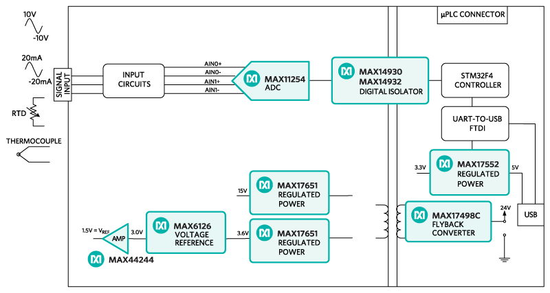 Figure 1. The MAXREFDES67# reference design block diagram.
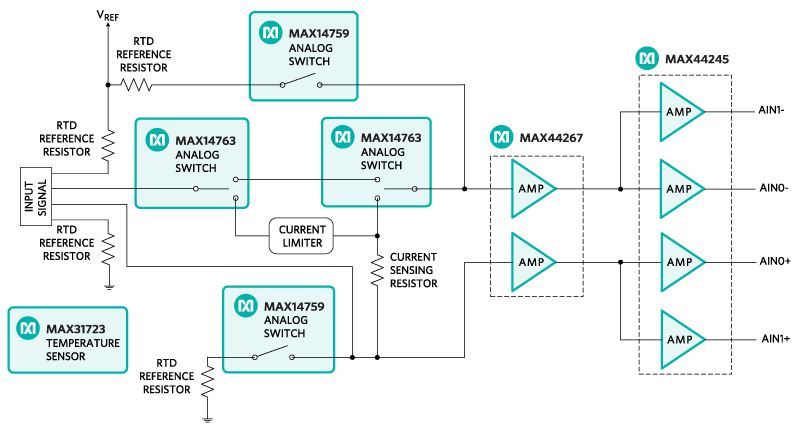 Figure 2. The MAXREFDES67# reference design input circuit block diagram.
Detailed Description of Hardware
The power requirement is shown in Table 1.
Table 1. Power Requirement for the MAXREFDES67# Reference Design
| Power Type | Input Voltage (V) | Input Current (mA, typ) |
|---|---|---|
| On-board isolated power | 24 | 20 |
Note: STM32 and FTDI are powered by USB separately
The MAXREFDES67# reference design is a universal analog input card with isolated power and data. It supports voltage, current, RTD (PT100 and PT1000), and thermocouple (K type) inputs as shown in the configuration diagram of Figure 3. The input circuitry utilizes the digitally controlled analog switches (MAX14759 and MAX14763) to make the appropriate electrical connections for different types of input signals, thus relieving the need for any additional jumpers on the terminal block. The dual beyond-the-rail op amp (MAX44267) buffers the input signal. The quad low-noise low-power op amp (MAX44245) attenuates and also adds 1.5V offset to the input signals. The offset voltage is needed because the ADC is set up to measure positive signals. This setup eliminates the need for a negative voltage reference and voltage supply. The 10:1.15 attenuation is for the -12V to +12V voltage signal, and the 10:9.53 attenuation is for the current, RTD, and TC input signals. The 10:1.15 attenuated signal from the output of the MAX44245 connects to channel 0 of the ADC, and the signal with 10:9.53 attenuation connects to channel 1 of the ADC. The STM32 controller determines which channel to read depending on the input selected. The MAX11254 is a highly integrated, 24-bit, 6-channel ADC with an integrated analog input PGA. The ADC’s reference input is driven by an ultra-high-precision voltage reference, the MAX6126, with 0.02% initial accuracy and a 3ppm/°C maximum temperature coefficient (tempco). An on-board digital thermometer (MAX31723) is placed close to the input terminal block to determine the temperature at the input port and provide the cold junction temperature of the thermocouple.
The MAXREFDES67# uses the ultra-efficient MAX17498C to generate the isolated +17.5V and +7.5V rails from a 24V supply. The two MAX17651 devices provide post-regulated +15V, +3.6V rails. The MAX14930/MAX14932 digital data isolators provide data isolation. The combined power and data isolation achieved is 300VRMS working voltage in pollution degree 2 environment based on material class IIIb per IEC 60950.
The MAX17552 step-down DC-DC converter converts the +5V supply from the USB to +3.3V and powers the STM32 microcontroller and FTDI USB-UART bridge.
A PT100 RTD and a K-type thermocouple are included in the MAXREFDES67# package. For the thermocouple, the yellow wire is the positive signal and the red wire is the negative signal.
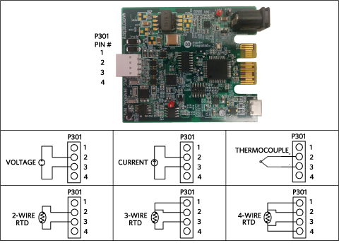 Figure 3. The MAXREFDES67# input configurations.
Detailed Description of Firmware
The MAXREFDES67# uses the on-board STM32F4 microcontroller to control the analog switch, read temperature from the digital thermometer, communicate with the ADC, and save the ADC samples in the on-chip SRAM. Users read the sampled data through a terminal program, allowing analysis on any third-party software. Users can also perform system and sensor calibrations through a terminal program. The red color VREF connector on the board is provided for RTD input calibration. The simple process flow is shown in Figure 4. The firmware is written in C using the Keil µVision5 tool.
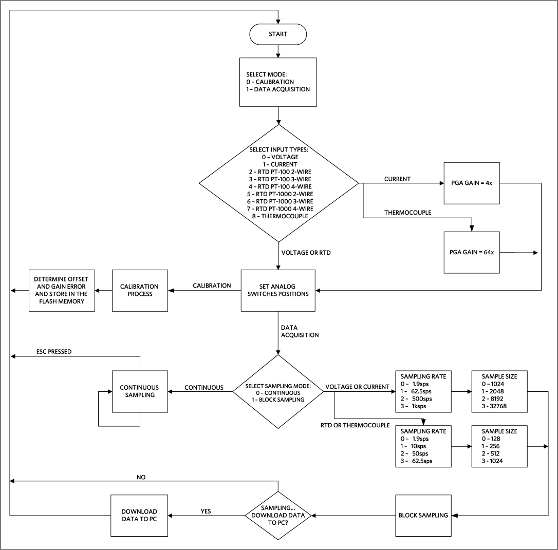 Figure 4. The MAXREFDES67# firmware flowchart.
The firmware accepts calibration and sampling commands, and is capable of downloading blocks of sampled data to a standard terminal program via a virtual COM port. The complete source code is provided to speed up customer development. Code documentation can be found in the corresponding firmware platform files.
Quick Start
Required equipment:
- Windows® PC with a USB port
- MAXREFDES67# board
- 24V power supply, provided
- PT100 RTD, provided
Procedure
The reference design is fully assembled and tested. Follow the steps below to verify board operation:
- The MAXREFDES67# utilizes the FTDI USB-UART bridge IC. If Windows cannot automatically install the driver for the FTDI USB-UART bridge IC, the driver is available for download from www.ftdichip.com/Drivers/D2XX.htm.
- Connect the 24V power supply to the J501 connector on the MAXREFDES67# board.
- Connect the RTD across pin 2 and pin 3 of the terminal block.
- Connect the USB cable from the PC to the MAXREFDES67# board.
- Open Hyperterminal or a similar terminal program on the PC. Find the appropriate COM port, usually a higher number port, such as COM4 or COM6, and configure the connection for 115200, 8-N-1 with no flow control.
- The MAXREFDES67# software will display a menu (Figure 5)
- Press 1 in the terminal program to select Data Acquisition.
- Press 2 to select RTD PT-100 2-wire input.
- Press 0 to select Continuous Sampling.
- Verify the measured temperature is approximately the room temperature.
 Figure 5. Terminal program main menu.
Lab Measurements
Equipment used:
- K-type Thermocouple (Omnitec EC3TC)
- PT-100 RTD 1/10 DIN (Omega P-M-1/10-1/4-6-0-G-3)
- Voltage calibrator DVC-8500
- Fluke 189 Multimeter
- Fluke 7341 Calibration Bath
- Omega HH41 Thermometer
- ETI Reference Thermometer
- Fluke 724 Temperature Calibrator
- Windows PC, a USB port
- MAXREFDES67# board
- +24V power supply
Voltage calibrator DVC-8500 and Fluke 189 multimeter were used to calibrate the inputs of the MAXREFDES67#.
Figure 6, Figure 7, Figure 8, Figure 9 show the DC histogram for 0V voltage input and 0A current input sampled at 1.9sps and 1ksps.
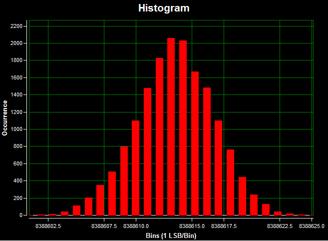 Figure 6. Voltage input DC histogram; a 0V input signal; a 1.9sps sample rate; 16384 samples; a code spread of 24 LSBs; a standard deviation of 3.273 (Effective Resolution = 22.3 bits); and the mean of 8µV.
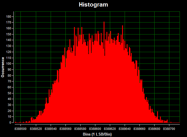 Figure 7. Voltage input DC histogram; a 0V input signal; a 1ksps sample rate; 16384 samples; a code spread of 210 LSBs; a standard deviation of 36.68 (effective resolution = 18.8 bits); and the mean of -7µV.
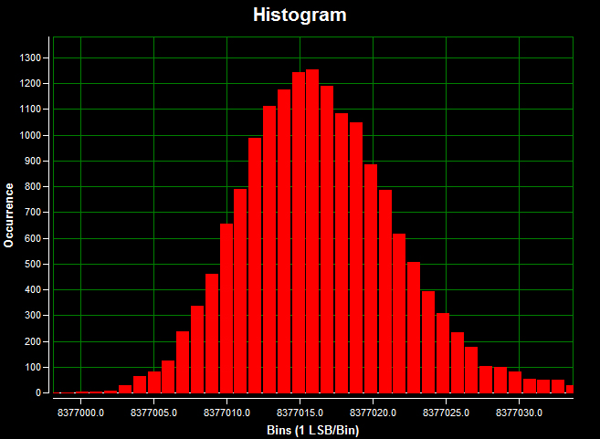 Figure 8. Current input DC histogram; a 0A input signal; a 1.9sps sample rate; 16384 samples; a code spread of 44 LSBs; a standard deviation of 5.643 (effective resolution = 21.5 bits); and the mean of 357nA.
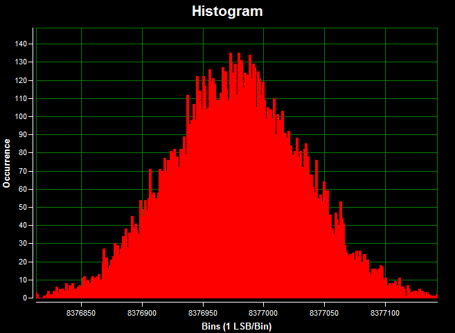 Figure 9. Current input DC histogram; a 0A input signal; a 1ksps sample rate; 16384 samples; a code spread of 441 LSBs; a standard deviation of 54.49 (effective resolution = 18.2 bits); and the mean of 470nA.
Figure 10 shows the temperature error measured by the MAXREFDES67# RTD input versus temperature referenced to three different thermometers. The references are the Omega HH41 thermometer, the ETI reference thermometer, and Fluke 724 temperature calibrator, respectively. The MAXREFDES67# connected RTD probe (Omega P-M-1/10-1/4-6-0-G-3) was placed in the Fluke 7341 calibration bath and calibrated at 20°C.
Figure 11 shows the temperature error measured by the MAXREFDES67# thermocouple input versus temperature referenced to the same three reference thermometers, the Omega HH41 thermometer, the ETI reference thermometer, and Fluke 724 temperature calibrator, respectively. The MAXREFDES67# connected K-type thermocouple probe was placed in the Fluke 7341 and calibrated at 20°C.
Click on the link below to see the NIST traceable certificate of calibration for the Omega HH41 thermometer used as a reference.
NIST traceable certificate of calibration for the Omega HH41 thermometer
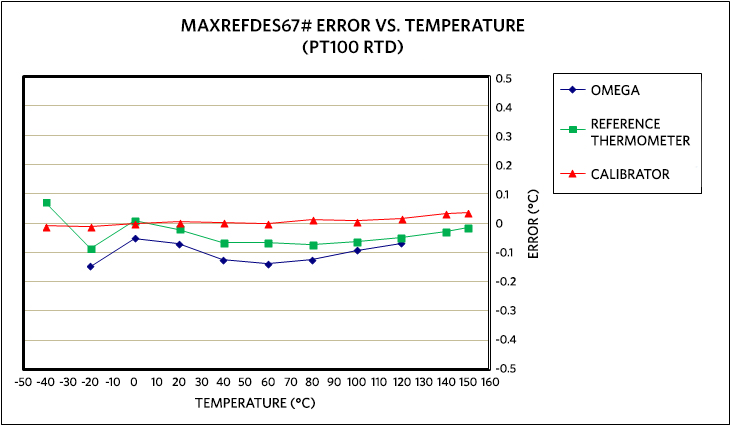 Figure 10. MAXREFDES67# error vs. temperature, using an Omega P-M-1/10-1/4-6-0-G-3, 4-wire RTD calibrated at 20°C.
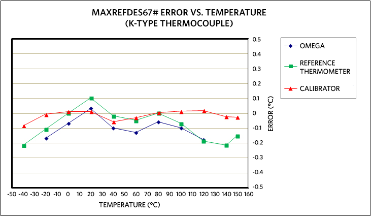 Figure 11. MAXREFDES67# error vs. temperature, using an Omnitec EC3TC, K-type thermocouple calibrated at 20°C.
For both Figure 10 and 11, the blue data used the Omega HH41 thermometer as a reference. The green data used the ETI reference thermometer as a reference. The red data used the Fluke 724 temperature calibrator as the reference.
Windows is a registered trademark and registered service mark of Microsoft Corporation.
Reference
- The new generation of manufacturing production is called Industry 4.0 in Germany and Smart Manufacturing System elsewhere. See, Securing the future of German manufacturing industry, Recommendations for implementing the strategic initiative INDUSTRIE 4.0, Final report of the Industrie 4.0 Working Group, Industry 4.0 Working Group, Acatech National Academy of Science and Engineering, April 2013, www.acatech.de/fileadmin/user_upload/Baumstruktur_nach_Website/Acatech/
root/de/Material_fuer_Sonderseiten/Industrie_4.0/Final_report__Industrie_4.0_accessible.pdf. Henceforth cited as Industrie 4.0. Although the Industrie 4.0 report is focused on Germany, the implications of the German research and findings are recognized for industry in other countries. See also Ferber, Stefan, “Industry 4.0 – Germany takes the first steps toward the next industrial revolution,” Bosch Software Group, Blogging the Internet of Things, October 16, 2012, http://blog.bosch-si.com/industry-4-0-germany-takes-first-steps-toward-the-next-industrial-revolution/.
There are many sources for Smart Manufacturing Leadership. An interesting summary report of issues and topics can be found at the Smart Manufacturing Leadership Coalition Committee Working Meeting, Minneapolis, MN, U.S., Thursday, October 20, 2011, https://smartmanufacturingcoalition.org/sites/default/files/smlc_meeting.pdf
Also see, Implementing 21st Century Smart Manufacturing, Workshop Summary Report, Smart Manufacturing Leadership Coalition, June 24, 2011, https://smartmanufacturingcoalition.org/sites/default/
files/implementing_21st_century_smart_manufacturing_report_2011_0.pdf.
A simple web search on the topic will reveal considerably more references.