MAXREFDES99#:MAX7219显示驱动器扩展板
概述
Maxim的MAXREFDES99#是Arduino®规格的扩展板,用于驱动标识应用中的16x16 LED点阵。设计可理想用于开发显示应用。电路板采用Maxim久负盛名的MAX7219驱动器,简化了控制多个阵列或数字显示形式LED的过程。MAXREFDES99#中,4片MAX7219 IC采用菊链配置,驱动完整的256点LED阵列,使阵列能够显示任意国际字符。电路板标配四个8x8 LED显示。
提供支持Arduino和ARM® mbedTM平台的MAXREFDES99#代码,可利用多种平台的电路板快速开发产品原型。系统演示包括显示ASCII字符‘空格’至‘~’,以及写/滚动字符串消息。鼓励开发者建立和增强代码库。
特性
- 灵活的16x16点阵显示
- mbed.org库
- Arduino库
- Arduino规格的平台
竞争优势
- 便携
- 紧凑
- 灵活
- 高成效
应用
- 显示屏
- 消费类电子
- 机器人技术


详情介绍
Introduction
LEDs, both low cost and available in many configurations, continue to dramatically transform signage and lighting. The MAX7219 has long been the developer’s best friend in LED driving, offering both simplicity and flexibility. Most systems, however, drive 8x8 arrays, limiting the amount of communication, specifically character size, and not utilizing the daisy chain feature of the MAX7219. 16x16 displays, in contrast, provide the capability to display most international alpha-numeric characters.
Enter the MAXREFDES99#, which drives a 16x16 display, making it a powerful tool for prototyping and developing applications.
The MAXREFDES99# is mbed and Arduino compatible, allowing fast development for both platforms. The shield contains four daisy-chained MAX7219s that drive four 8x8 red LED dot-matrix displays installed on the top arranged to make a 16x16-matrix display.
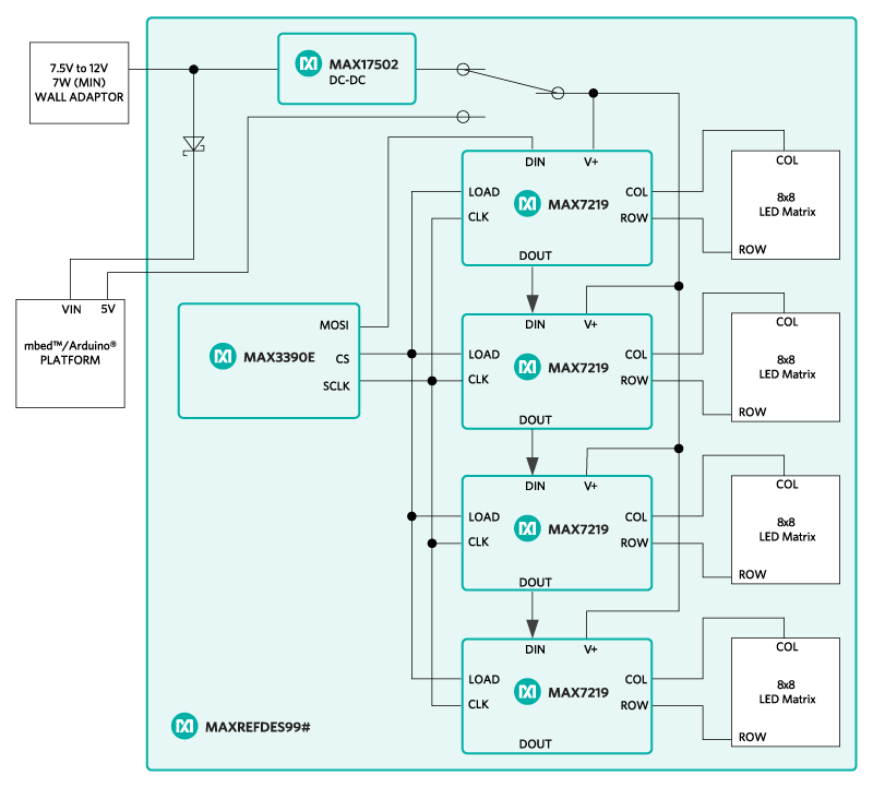
Figure 1. The MAXREFDES99# reference design block diagram.
Detailed Description of Hardware
See Figure 1 for a block diagram of MAXREFDES99#.
MAXREFDES99# can be powered from a wall-wart which provides a minimum of 7W of power and an output voltage in the range of 7.5VDC to 12VDC. 7W is enough power for the display, plus the microcontroller platform being used through the VIN pin of the target platform. The reference design can be optionally powered from a USB port while developing application code, however, the user must take care not to exceed the power capabilities of the 5V rail supplied by their platform. The recommended method of powering MAXREFDES99# is through a wall-wart connected to J1.
MAXREFDES99# uses the MAX3390E level translator to provide a 3.3V logic-level compatible interface to the four MAX7219 display drivers when using the shield with 3.3V platforms. The serial interface between the platform and the shield uses D10, D11, and D13 for LOAD, DIN, and CLK respectively. The four MAX7219 display drivers are daisy-chained connected with D11 connected to U3 and DOUT of U3 connected to DIN of U4 and so on. DOUT of U6 is left unconnected.
Detailed Description of Firmware
Libraries have been developed for both Arduino platforms and the online development environment mbed.org which supports microcontrollers from several manufacturers of ARM Cortex®-M microcontrollers. The source code for these libraries and their corresponding 'Hello World' demo programs can be found in the design files, or at the following links.
- Arduino
- mbed
Figure 2 provides a high-level flow chart of the demo program for both platforms.

Figure 2. Demo program flowchart.
Quick Start
Required equipment:
- Windows® PC with a USB port
- MAXREFDES99#
- Compatible Arduino form-factor mbed platform
- 7W min Wall-Wart with 7.5VDC to 12VDC output
Procedure
The reference design is fully assembled and tested. Follow the steps below to verify board operation.
- Connect MAXREFDES99# to your platform.
- Connect wall-wart to J1 of MAXREFDES99#
- Connect USB cable from the PC to your platform.
- Follow the appropriate instructions below:
- Arduino
- Download the library from the GitHub repository
- Follow the instructions here for installing third party libraries.
- Open your Arduino IDE, version 1.6.7 or later.
- Navigate to File/Examples/MAX7219/MAXREFDES99_example
- mbed
- If you have never used mbed, setup an account and add your platform to your online compiler per the instructions on your platform's product page.
- If you are using Windows and have never used serial communications between your PC and your mbed platform, follow the instructions here.
- Navigate your browser to this link.
- Click the 'Import this program' button and import the demo as a 'program'
- Arduino
- Compile and download the resulting binary to your platform.
- Open Hyperterminal, or your favorite terminal emulator, find the appropriate COM port for your platform, and configure the connection for 9600bps, 8-N-1 with no flow control.
- Ensure your terminal settings are configured for 'Auto' on Receive and 'CR+LF' on transmit.
- Press the reset button on your platform and exercise the demo.
- When running endless loops on the display, press the reset button on the platform to stop the loop and return to the main menu.
Arduino is a registered trademark of Arduino LLC.
ARM and mbed are registered trademarks of ARM Limited.
Cortex is a registered trademark of ARM Limited.
Windows is a registered trademark and registered service mark of Microsoft Corporation.