MAXREFDES117#:心率和脉搏血氧监测器
MAXREFDES117#参考设计是低功耗、光学心率模块,集成红光和红外(IR) LED以及电源。微小的电路板非常适合可穿戴项目,可穿戴在指尖或耳垂,高精度检测心率。这款通用模块同时支持Arduino和mbed平台,便于快速测试、开发和系统调试。示例固件中提供基础、开源的心率和SpO2算法。
电路板具有8个缝纫垫,用于安装以及快速连接到开发平台。
与所有的Maxim参考设计一样,设计资源选项卡提供BOM、原理图、布局文件以及Gerber文件。此外,有电路板可供购买。
特性
- 光学心率监测和脉搏血氧方案
- 微型12.7mm x 12.7mm (0.5in x 0.5in)电路板尺寸
- 低功耗
- 器件驱动器
- 免费算法
- 示例C语言源代码,支持Arduino和mbed平台
- 测试数据
竞争优势
- 高度集成、小尺寸传感器
- 非胸带心率/SpO2检测
- 超低功耗
应用
- 可穿戴设备
- 心率监测仪
- 脉搏血氧仪


详情介绍
Introduction
Wearable devices hold the potential to transform health and medical monitoring. Heart rate, specifically, provides tremendous insight into heart function and health, during both activity and rest. Innovation and development of both optical semiconductors and lower-power integrated circuits makes the transition to wearables possible. Until now, only large organizations, with deep development budgets, could deliver such advanced products.
MAXREFDES117# delivers the promise of wearable devices to all developers. This unique design measures both heart rate and pulse oximetry. MAXREFDES117# features the MAX30102 with integrated red and IR LEDs for heart-rate and SpO2 detection. This configuration ideally detects heart rate and pulse ox on a person’s fingertip, earlobe, or other fleshy extremity. The small board size of 12.7mm x 12.7mm (0.5in x 0.5in) is ideal for wearable applications and may be stitched into fabric for immediate prototyping. Firmware is available for both Arduino and mbed platforms, enabling users to develop with virtually any platform. User needs to provide a 2V to 5.5V supply at the power input, perfect for virtually any battery or Arduino and mbed form-factor board.
The MAXREFDES117# design utilizes the heart-rate/SpO2 sensor (MAX30102), an efficient, low-power step-down converter (MAX1921), and an accurate level translator (MAX14595). The entire design typically operates at less than 5.5mW when using with the example firmware. A block diagram of the system is shown in Figure 1.
System Diagram
 Figure 1. MAXREFDES98# reference design block diagram.
The power requirement is shown in Table 1.
Table 1. Power Requirement for the MAXREFDES117# Reference Design
| Input Voltage (V) | Input Current (mA, typ) |
|---|---|
| 2V to 5.5V | 1.5mA (3.3V input) |
Note: Controller board is powered separately
The MAXREFDES117# reference design is a PPG-based heart-rate and SpO2 monitor subsystem. The circuit utilizes the MAX30102 heart-rate/SpO2 sensor with integrated red and IR LEDs. The step-down converter MAX1921 converts the 2V to 5.5V supply input and generates the 1.8V rail for the heart-rate sensor. The MAX14595 level translator provides an interface between the heart-rate/SpO2 sensor and the controller board, which generally use a different logic level.
Detailed Description of Firmware
The MAXREFDES117# can be used with virtually any microcontroller that has I2C interface. The Arduino and mbed example firmware have been tested on the following development platforms:
mbed:
- Maxim Integrated MAX32600MBED#
- Freescale FRDM-K64F
- Freescale FRDM-KL25Z
Arduino:
- Adafruit Flora
- Lilypad USB
- Arduino UNO
Users may read sampled data, calculated heart rate and SpO2 through a terminal program, allowing analysis on excel or any third-party software. The simple process flow is shown in Figure 2.
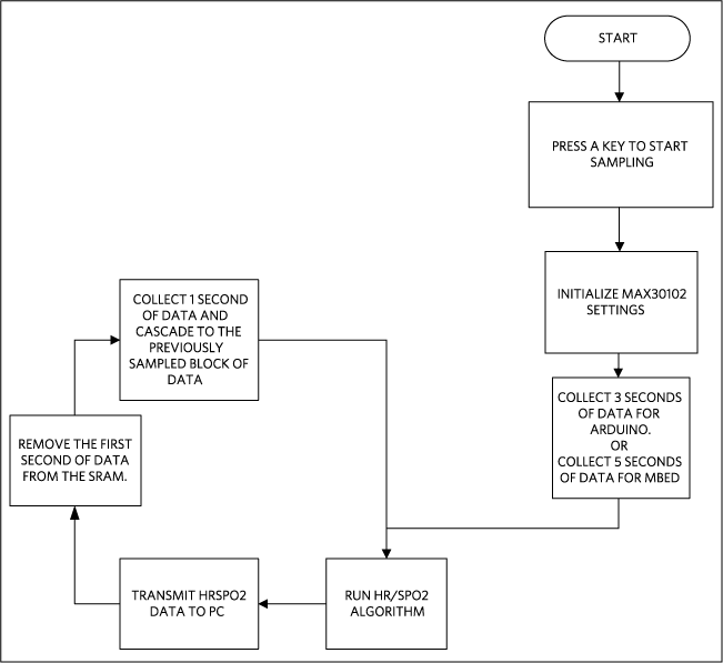 Figure 2. The MAXREFDES117# firmware flowchart.
The complete source code, including the heart rateheart-rate/SpO2 algorithm, is provided to accelerate development. Code documentation can be found in the corresponding firmware platform files.
Heart rateHeart-rate accuracy varies depending on the chosen platform. The tested mbed platforms give more accurate heart-rate/SpO2 calculations than the tested Arduino platforms because the mbed platform controllers have more SRAM than the Arduino platform controllers. For the example firmware, mbed platforms store 5 seconds of samples collected at 100sps, while the Arduino platforms store 4 seconds of samples collected at 25sps.
SpO2 calculation is based on the equation shown below. However, determining the constants (C1, C2, and C3) requires a comprehensive clinical study of pulse pulse-oximetry data from a statistically significant population set using this hardware. Such a clinical study is beyond scope of this design. Therefore, the calculated SpO2 value may havecan have an error.
SpO2 = C1 × AverageRatio2 + C2 × AverageRation + C3
Where AverageRatio is the average ratio of IR and red LED readings. C1, C2, and C3 are constants.
Quick Start
Required equipment:
- Windows PC with a USB port
- MAXREFDES117# board
- 5 cables that can be used to connect the MAXREFDES117# with the controller board
- One of the supported mbed or Arduino controller boards listed above
- One USB cable that is compatible with the selected controller board
Download, read, and carefully follow each step in the appropriate MAXREFDES117# quick Start Guide:

Lab Measurements
Equipment used:
- MAX32600MBED#
- Adafruit Flora
- Adafruit BlueFruit
- Polar H7 Bluetooth Smart Heart RateHeart-Rate Sensor
- Android tablet
Figure 3 and Figure 4 show how the MAXREFDES117 calculated heart rate compared to the Polar H7 chest strap. The data in Figure 3 were taken while the person was sitting still for 20 minutes. And the data in Figure 4 were taken while the person was walking at a normal speed for 20 minutes.
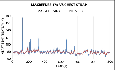 Figure 3. For sedentary test, over 99% of the mbed + MAXREFDES117# heart heart-rate data are less than 5 beats/min delta from the Polar H7 chest strap.
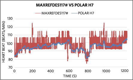 Figure 4. For moving test, over 92% of the Arduino + MAXREFDES117# heart- rate data are less than 10 beats/min delta from the Polar H7 chest strap.