MAXREFDES150# Pocket IO PLC开发平台
工业4.0是第四次制造和过程自动化革命,为PLC设计工程师带来了巨大挑战:将更多的功能集成到越来越小的封装内。越来越高的I/O密度和越来越小的封装尺寸也带来了另一项基本的设计挑战:必然的功耗问题。系统的电源效率必须比以往更高,避免PLC过热,尤其在通常不能使用风扇和通风孔的应用中。幸运的是,Maxim Integrated等公司正在开发新方案,使其整合能力在变革中的工业市场中大放异彩。


特性
- 两路模拟输入通道,±12V、24位ADC
- 两路模拟输入通道,±24mA、24位ADC
- 模拟输出通道,0V至±12V、16位DAC
- 八路数字输入通道,36V (最大值),可配置为IEC® 61131-2输入类型1、2和3
- 八路数字输出通道;640mA高边开关或640mA推挽式输出@24V
- 两个RS-485 COM端口;半双工、高达42Mbps数据率
- 三个直流电机控制器:9V至32V全桥直流电机驱动器,高达2.5A峰值电机电流(由独立电源供电)
- 四个IO-Link主机端口,采用M12孔头连接器
- 完全兼容IO-Link 1.1版
- TEConcept IO-Link主机栈
应用
- 工厂和过程自动化
- 楼宇自动化
- 机器人控制
- 快速搭建新型工业控制系统原型
- IO-Link传感器和执行器
MAXREFDES150# 组件
- Pocket IO:MAXREFDES150MAIN#和MAXREFDES150LED#,安装在塑料外壳中,含Intel Edison开发模块
- 连接器安装板——MAXREFDES150ATACH#
- 40引脚孔头/孔头电缆套件——每套两根
- USB A至micro-USB B转换器
- AC至DC (24VDC、1A)电源,含适用于当地插座的适配器
详情介绍
概况
工业4.0是第四次制造和过程自动化革命,为PLC设计工程师带来了巨大挑战:将更多的功能集成到越来越小的封装内。越来越高的I/O密度和越来越小的封装尺寸也带来了另一项基本的设计挑战:必然的功耗问题。系统的电源效率必须比以往更高,避免PLC过热,尤其在通常不能使用风扇和通风孔的应用中。幸运的是,Maxim Integrated等公司正在开发新方案,使其整合能力在变革中的工业市场中大放异彩。
Detailed Description of Hardware
Pocket IO is the brand name for MAXREFDES150#. The MAXREFDES150# consists of three different boards. The overall system block diagram is shown in Figure 1.
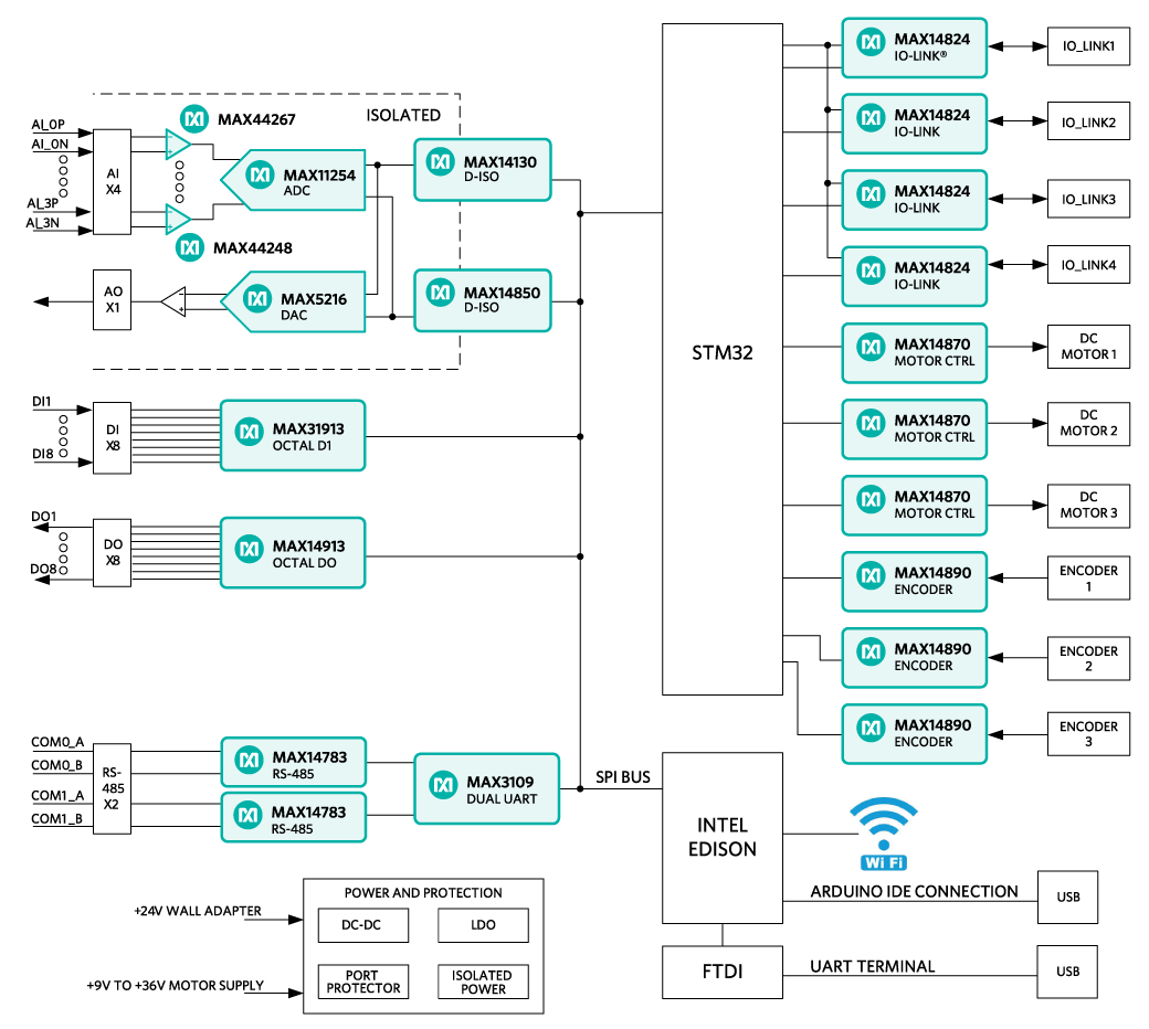 Figure 1. MAXREFDES150# system block diagram.
The ICs for the main functional blocks are within the Pocket IO case (the two boards are MAXREFDES150MAIN# and MAXREFDES150LED#) while the connectors are on a separate board (called MAXREFDES150ATACH#) which connects to Pocket IO using two 40-pin cable assemblies.
The control program for Pocket IO runs on the Intel Edison board, which is mounted on the MAXREFDES150MAIN# board. Separate STM microcontrollers are used to support the IO-Link masters (TEConcepts stack) and the DC-motor drivers.
Power Supplies
A single 24V, 1A supply is used to power the Pocket IO and internal DC-DC, and LDO circuits are used to generate the various different voltage levels required by the analog and digital devices. Note: The maximum load this adapter can supply is 1A, which limits how many of the digital outputs are switching loads simultaneously since each of the eight outputs can handle loads of up to 640mA each. The user can use a different 24V supply with 5A (max) capacity. The 24V, 1A supply connects to the block barrel connector, shown on the left in Figure 2.
Pocket IO has three DC-motor controllers, each of which can support +9V to +32V full-bridge DC-motor drivers at up to 2.5A peak motor current. In order to support these higher voltages and currents, a separate user-supplied power supply is required, and connects to Pocket IO through the green three-way terminal. Terminal 1 is used (with Terminal 3) to test the polarity of the external supply (to protect Pocket IO motor drivers from reverse polarity connections). In normal-use mode Terminal 2 is the +9V to +32V connection and Terminal 3 is the ground or 0V connection.
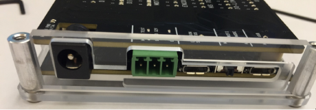 Figure 2. MAXREFDES150# power inputs.
Connections
The main functional blocks are on the two PCBs within the Pocket IO case while the connectors are on a separate board, called MAXREFDES150ATACH# shown in Figure 3.
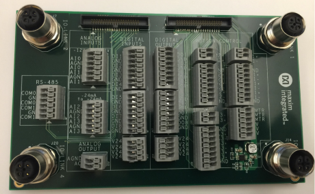 Figure 3. MAXREFDES150ATACH#.
LED Indicators
Figure 4 explains the functions of the LED indicators for MAXREFDES150#.
 Figure 4. Pocket IO LEDs.
Detailed Description of Software
When building up a quick application, or when prototyping some feature, the quickest and easiest way to program Pocket IO, is through the Arduino application. Though not a full-code development, debugging environment, the Arduino sketch technique has a lot to offer, including:
- A familiar interface, instantly recognizable by many
- A full C/C++ compiler
- Access to many useful features built into the Linux OS resident in the Intel Edison processor
- Access to Pocket IO features through an included library
- Access to library updates as they become available
With so much capability packed into one small enclosure, the interface to manage all this is crucial. Each of Pocket IO's 10 resources has its own API. Figure 5 shows the software architecture for Pocket IO using Arduino IDE to compile code to run on the onboard Intel Edison CPU.
 Figure 5. Pocket IO software architecture.
The following sections are details about API and some techniques, many Linux-specific, that enhance the capability of your applications.
Detailed Pocket IO API
These sections, organized alphabetically by Pocket IO feature, details the API available to control Pocket IO through sketch.
Note: For information about how to access software revision codes from Pocket IO, consult Boardinfo.ino in the Pio section of the Examples in sketch.
Analog Input
Pocket IO features two analog voltage inputs and two analog current inputs, all easily accessible through sketch. The voltage channels read anything between -12V and +12V whereas the current channels read anything between -24mA and +24mA. Pocket IO features a MAX11254 24-bit ADC featuring built-in two-point calibration compensation, which the API accommodates.
The API selects from among four channels, as follows:
| Channel | API Mnemonic | Attach Board Symbol |
|---|---|---|
| First Voltage | AI0 | AI0+/AI0- |
| Second Voltage | AI1 | AI1+/AI1- |
| First Current | AI2 | AI2 AI2+/AI2- |
| Second Current | AI3 | AI3 AI3+/AI3- |
Note: The analog input and output circuitry grounds are isolated from the ground of the rest of Pocket IO. The AGND labels on the attach board indicate this separate analog ground. If you accidentally return an analog signal, either from one of the analog inputs or from the analog output, to the more common GND, there can be unexpected results.
Calibration
The following code snippet shows how to perform a two-point calibration. Commonly, the user locks in the calibration, so it does not need to be done again, and calibration rarely needs to be done. Calibration comes in handy when attaching further circuitry to the analog inputs, and accuracy is to be maintained ahead of this extra circuitry. Pocket IO comes factory-calibrated for best accuracy at the connection points of the attach board.
The code snippet uses port AI0 as an example, but the code is the same regardless of which port is being calibrated. Each channel keeps its own unique calibration parameters.
// Makes Pocket IO analog input API available
// #include
PioAi pioAi; // Instances an analog input interface object
pioAi.init(); // Always needed for analog input pioAi.initCal(AI0); //Commences calibration
/*
* Put code here to apply +12 volts at the point of calibration
* if channel AI0 or channel AI1, or to apply +24mA if channel
* AI2 or AI3.
*
* Do not proceed until the voltage or current is applied and * stable.
*/
pioAi.setFullCal(AI0); // +12V or +24mA measured
/*
* Put code here to apply 0 volts or -24mA at the point of
* calibration.
*
* Do not proceed until the voltage or current is applied and * stable.
*/
pioAi.setZeroCal(AI0); // 0V or -24mA measured
delay(1000); // needed for ADC to calc corrections
// This method call takes the required corrections for that
// channel and stores it in non-volatile memory
pioAi.storeCal(AI0);
Reading an Analog Sample
Samples can be read either as a float or as a raw binary code from the ADC. The following code snippet shows how it is done. Because the sample rate is determined by the ADC itself, the user must select from one of the MAX11254 sample times as shown in the following table. Longer sample times result in readings with lower noise. This affects multiple sample reads. For example, with AI_RATE_1_9_SPS, after a first read, the thread calling a read method a second time is blocked for about 526msec.
| MAX11254 Sample Rate (sps) | API Mnemonic |
|---|---|
| 1.9 | AI_RATE_1_9_SPS |
| 15.6 | AI_RATE_15_6_SPS |
| 31.2 | AI_RSTE_31_2_SPS |
| 62.5 | AI_RATE_62_5_SPS |
| 250 | AI_RATE_250_SPS |
| 500 | AI_RATE_500_SPS |
| 1000 | AI_RATE_1000_SPS |
// Makes Pocket IO analog input API available
//
#include // no init() method
PioAi pioAi; // instances an analog input interface object
pioAi.init(); // always needed for analog input
// Loads a previously stored calibration for that channel,
// usually done once at setup
//
pioAi.restoreCal(AI0);
>while (XXX)
{
>// Reads one sample as a raw binary code
//
uint32_t code = pioAi.readCode(AI0, AI_RATE_1_9_SPS);
// The returned code is in offset binary, where 0V is
// 2^23, 12V is 2^23+2^23 = 2^24, and -12V is // 2^23 – 2^23 = 0
//
// In the case of current, the calibration is done is
// firmware, so the returned code is not relevant
// float toVolts = (float) (code – 8388608) * 12.0 / 8388608;
// Or you can do it easier this way, for reading current,
// this is the best way.
// float volts = pioAi.readFloat(AI0, AI_RATE_1_9_SPS);
}
Analog Output
Pocket IO provides one analog output, capable of any output voltage between 0V and 12V. Since there is only one analog output channel, there is no need to select channels. The API consists of only one method call, and no init() is needed for analog out.
The call to the method is a raw 16-bit code to the DAC. To drive a specific voltage, it must first be converted to a 16-bit equivalent for the DAC, as shown in the code snippet below.
// Makes Pocket IO analog output API available
// #include PioAo pioAo;
// instances an analog output interface object
const float DAC_CONV = 5443.106; // codes per volt
float voltageOut = 1.250; // desired output voltage
uint16_t codeDAC = (uint16_t) (voltageOut * DAC_CONV);
// Returns the argument to the method, as a uint16_t, which
// is usually ignored
//
uint16_t intCodeDAC = pioAo.writeCode(codeDAC);
// Could also do it this way
// uint16_t intCodeDAC = pioAo.writeCode(voltageOut * DAC_CONV);
Communications (RS-485)
Pocket IO provides serial communication through two RS-485 ports. Each port is half-duplex, and is preset for 115.2KBAUD at 8N2 (eight data bits, no parity, two stop bits).
Select from among the 2 channels as follows:
| Channel | API Mnemonic | Attach Board Symbol |
|---|---|---|
| 0 | COM0 | COM0A/COM0B |
| 1 | COM1 | COM1A/COM1B |
The API permits independent reading and writing for each channel. For any given channel, writes supersede reads. No harm occurs if multiple RS-485 transceivers drive a bus at the same time though this means any received data would be corrupted. Use protocol to ensure only one transceiver drives the bus at a time.
// Makes Pocket IO COMMS API available
// #include PioCom
pioCom; // instances a COMMS interface object
pioCom.init(); // always needed for COMMS
uint8_t bytes = {‘H’, ‘e’, ‘l’, ‘l’, ‘o’, ‘,’,’ ‘, ‘W’, ‘o’, ‘r’, ‘l’, ‘d’, ‘!’, \0};
// First param must be either COM0 or COM1
// Second param is a pointer to an array of bytes
// Third param is the number of bytes to transfer
//
// Maximum of 128 bytes can be sent. If a previous write
// has not yet completed, then the number of bytes that
// can be written is 128 – (number of bytes left to send)
// // If you send more than 128 bytes, the transmitted data
// will be corrupted. // PioCom.write (COM0, bytes, sizeof(bytes));
Reading data from an RS-485 port is similar to writing, with the added complication that you do not necessarily know how many bytes have been received. The following code snippet shows how to read data.
// Makes Pocket IO COMMS API available
//
#include PioCom pioCom;
// instances a COMMS interface object pioCom.init();
// always needed for COMMS
// Needed once before first read
// pioCom.clearInterrupts(COM0); uint8_t receiveBuffer [100]; uint8_t receiveCount;
// First param must be either COM0 or COM1
// Second param is an array to receive data
// Third param is the size of the buffer
// Fourth param will get the number of bytes actually read
//
// The receive buffer will be filled with a number of bytes
// received since a previous read method call. If this is less
// than the size of the buffer, then the buffer is
// partially filled. Otherwise, the buffer is filled and
// a subsequent read can obtain further read data.
//
// Note that data will be corrupted if more than 128 bytes
// have been received since a previous read method call.
//
// If there is no data, the fourth param will be set to zero
//
pioCom.read(COM0, receiveBuffer,
sizeof(receiveBuffer), &receiveCount);
// Do you want to test if there is pending data to be
// received? This method call returns the number of // bytes waiting to be read
//
// Useful for conditional mutex
//
uint8_t howManyBytes = pioCom.readRxFifoLevel(COM0);
Digital Input
Pocket IO has eight individual IEC-compliant industrial digital inputs. These inputs connect to binary sensors, such as limit switches, proximity sensors, distance sensors, and user switches. These inputs can be read individually, or as a group, through sketch.
Eight LEDs on the display panel indicate the state of each of these digital inputs. The LEDs are extinguished if driven low or left open, and illuminate when the corresponding input is driven logic high. The following table connects the individual inputs to the values returned through the API
| Channel | Bit Mask | API Mnemonic | Attach Board Symbol |
|---|---|---|---|
| 1 | 0x01 | DI1 | DI1 |
| 2 | 0x02 | DI2 | DI2 |
| 3 | 0x04 | DI3 | DI3 |
| 4 | 0x08 | DI4 | DI4 |
| 5 | 0x10 | DI5 | DI5 |
| 6 | 0x20 | DI6 | DI6 |
| 7 | 0x40 | DI7 | DI7 |
| 8 | 0x80 | DI8 | DI8 |
Additionally, the user has access to the debounce feature of the MAX31913 industrial digital input device. This feature reduces chattering of particularly noisy digital inputs. This debounce is global, applying to all digital inputs simultaneously used by Pocket IO. The following code snippet shows how to access these inputs as well as how to manage debounce.
// Makes Pocket IO digital input API available
//
#include PioDi pioDi;
;// Instances a DI interface object pioDi.init();
pioDi.init(); // always needed for DI
// Gets all 8 inputs at once, correspondence between
;
// bits and inputs given in the table above
// uint8_t allDigitalInputs = pioDi.readInput();
// Overloaded method also reads individual digital input
// channels. Returns ‘0’ or ‘1’
//
// In this case, checks the state of channel 7 only
// uint8_t specificDigitalInput = pioDi.readInput(DI7);
// This is how to set the debounce. Set as follows:
// 0x00 – no debounce
// 0x01 – 25usec of debounce
// 0x02 – 750usec of debounce
// 0x03 through 0xff – 3msec of debounce
//
// A possibly corrected value is returned, for example if you
// try to set 0x10, 0x03 will be returned
// uint8_t realDebounce = pioDi.writeDebounce(0x02);
// The currently operational debounce setting can be checked
// uint8_t whichDeboucne = pioDi.readDebounce();
Digital Output
Pocket IO supports eight industrial digital outputs, each capable of driving 24V at greater than 640mA. The API supports many of the features of the MAX14913 or MAX14912 digital output driver IC, including output modes and fault detection.
Each digital output channel can be in one of two modes. High-side mode, as its name implies, only drives a channel high (nominal 24V). Many existing actuators and indicators work best in high-side mode. To have faster output driver switching, each output channel can also be configured to push-pull mode. Since both a high and a low are actively driven, there is no longer a natural decay of the wiring slowing down the transitions from high to low. The following table shows how to specify these through the API.
| Mode | API Mnemonic |
|---|---|
| High-Side | HS_MODE |
| Push-Pull | PP_MODE |
Each individual digital output can be driven high or low. The Pocket IO front panel allows easy confirmation of the output state, illuminating a green LED for each output being driven high. A matching red LED indicates that a fault has occurred on that output. This most commonly happens when accidentally tying two digital outputs together when they drive conflicting logic levels.
| Channel | Bit Mask | API Mnemonic | Attach Board Symbol |
|---|---|---|---|
| 1 | 0x01 | DO1 | DO1 |
| 2 | 0x02 | DO2 | DO2 |
| 3 | 0x04 | DO3 | DO3 |
| 4 | 0x08 | DO4 | DO4 |
| 5 | 0x10 | DO5 | DO5 |
| 6 | 0x20 | DO6 | DO6 |
| 7 | 0x40 | DO7 | DO7 |
| 8 | 0x80 | DO8 | DO8 |
The following code snippets show how to command the digital outputs and manage the mode settings of Pocket IO.
// Makes Pocket IO digital output API available
// #include PioDo pioDo;
// instances a DO interface object
// no init() method
// Commonly, set the output mode once before
// driving outputs
//
// first param:
// - 0x00 means set all to high-side more
// - 0x01 – 0xff means set all to push-pull mode
// pioDo.setModeAll(PP_MODE);
// can also set the mode of individual outputs
// here, half of the outputs are set to high-side
// for (int i = DO5; i <= DO8; i++) { pioDo.setMode(i, HS_MODE); }
// The mode can be confirmed through this method call
;
;
{ // code here for push-pull
} else {
// code here for high-side
}
The Pocket IO display panel indicates fault conditions on digital outputs by illuminating a red LED. This fault condition can also be detected through the API. There is a lot more to faults than can be described here, so for more details about fault conditions, refer to the MAX14912/MAX14913 data sheet.
// Is there a fault condition on digital output channel 4?
//
// The second argument indicates whether to clear faults or
// not. True causes faults to be cleared.
//
if (pioDo.readFault(DO4, false))
{
// we have a fault on DO4
}
// grab all the fault conditions at once
// If (pioDo.readFaultAll(true) & 0x0f)
{
// we have a fault on one or more of
// DO1 through DO4
}
Edison LED
Some Pocket IO resources are not directly related to industrial inputs and outputs. One of these resources is the two LED at the left of the display panel, labelled “EDISON STATUS.” One red and one green LED are purely under the user’s control. The LEDs can be used to indicate progress, status, or activity.
The following code snippet shows how to access the LEDs.
PioEdLed pioEd;
;// Instances an Edison LED object pioEd.init();
// Always needed for Edison LED while (true)
{ pioEd.writeLed(GREEN, 0x01); // illuminate
delay(500);
pioEd.writeLed(RED, 0x01);
delay(500); pioEd.writeLed(GREEN, 0x00);
// extinguish delay(500);
pioEd.writeLed(RED, 0x00);
}
Encoders
Pocket IO has the capability to manage up to three motion-control channels. For many motion-control applications, controlling a motor is enough. For more precise scenarios, feedback is obtained, often from incremental encoders. This section discusses the three incremental encoder interfaces built into Pocket IO.
Incremental encoders communicate position information through two (most common), three (somewhat common) or four (less common) signals. Two-signal encoders are called A and B. Each edge communicates some fraction of a revolution. For example, when using a 4,000 pulses-per-revolution encoder, if you count only the rising edges of the A signal, you can see 1,000 such edges per revolution of the encoder shaft. If you count all edges of both the A and B signals, you can see 4,000 such edges per revolution of the encoder shaft. The timing of the A and the B signals is such that the direction can also be unambiguously determined. The Pocket IO incremental encoder interface uses the A and the B signals to maintain a position count based on the rising edges of the A signal.
A third signal, if it exists, is labelled the Z signal. Sometimes called an index pulse, this optional signal indicates the zero-degree point of the encoder shaft. Pocket IO currently ignores the Z signal. If a fourth signal exists, it is usually labelled the Y signal, and is used to indicate a fault condition in the encoder. Pocket IO has no means to connect to a Y signal.
Incremental encoders have been around for many decades now. Because of this, these encoders are available in a variety of signaling formats, and the MAX14890E encoder used in pocket IO is designed to handle this multiplicity.
Each signal has a “+” connection point and a “-” connection point. For example, the first encoder A signal connects through signals A1+ and A1-. How these are connected to depends on whether the signal format is single-ended or differential. For example, to connect a TTL A encoder signal to Pocket IO encoder channel 1, tie the signal to A1+, and tie the return to A1-. For differential signaling, tie the encoder A+ signal to A1+ and the encode A- signal to A1-. Because of the large common mode tolerance range of the MAX14890E used in Pocket IO, differential encoders usually function well even with no grounds tied between the encoder and Pocket IO.
Several front-panel LED indicators speak to the encoder interface. The yellow LED in the ENCODER section indicates encoder activity whereas the corresponding red LED indicates that an encoder channel has experienced a fault situation. Additionally, the yellow LED in the HS TERM section illuminates when Pocket IO attaches the high-speed RS-422 termination to the corresponding encoder channel.
Each Pocket IO encoder channel has its own signal format selection, communicated to the API by consulting the following table.
| Standard | API Mnemonic |
|---|---|
| Single-ended | SEHTL |
| Differential HTL | DHTL |
| RS-422 | RS422 |
| TTL | TTL |
Select from among the 3 encoder channels as follows:
| Channel | API Mnemonic | Attach Board Symbols |
|---|---|---|
| 1 | ENC1 | A1+, A1-, B1+, B1-, Z1+, Z1- |
| 2 | ENC2 | A2+, A2-, B2+, B2-, Z2+, Z2- |
| 3 | ENC3 | A3+, A3-, B3+, B3-, Z3+, Z3- |
This code snippet shows how to set encoder signal formats, and how to obtain encoder information.
// Make Pocket IO encoder API available
// #include PioEnc pioEnc;
// Instances an encoder interface object pioEnc.init();
// Always needed for encoders
// This sets the encoder 3 signal mode to TTL
// pioEnc.setMode(ENC3, TTL);
// The encoder interface maintains a position for each
// encoder. The position count is incremented for each
// clockwise pulse obtained by the encoder, and is
// decremented for each counterclockwise pulse of the
// encoder. So, if you read a position, move 500 pulses
// clockwise, then 499 pulses counterclockwise, your new
// position will be one count higher than the previous // position.
//
// The position is maintained as a 32-bit int, so commonly
// no overflow/underflow maintenance is needed in code.
//
// This is how to obtain the current position of encoder 1
// int positionNow = pioEnc.getCount(ENC1);
// You can also reset the encoder to zero at any time.
// pioEnc.initCount(ENC1);
Motor Control
A nice feature of Pocket IO is the ability to control up to three brushed DC motors. A separate green-colored connector supplies the motors, permitting the use of motors from 4.5V to 32V. During startup and other high-speed changes, each motor is limited to about two amperes of drive current. Because the motor driver is a full-bridge MAX14870 device, there is no ground connection to the motor, only to its two terminals.
The Pocket IO indicator panel shows the motor driving state for each motor port. A green LED illuminates when driving a motor clockwise, and a yellow LED illuminates when driving a motor counterclockwise. The higher the speed, the brighter the LED.
To adjust motor speed, Pocket IO provides an 8-bit PWM control for each motor independently. Select from among the 3 motor channels referring to the following table:
| Channel | API Mnemonic | Attach Board Symbol |
|---|---|---|
| 1 | M1 | M1+/M1- |
| 2 | M2 | M2+/M2- |
| 3 | M3 | M3+/M3- |
The API maintains a concept of rotation direction. When driving clockwise, the “+” connection averages a higher voltage than the “-“ connection. When driving counterclockwise, the “+” connection averages a lower voltage than the “-“ connection. The following table shows how to describe this.
| Direction | API Mnemonic |
|---|---|
| Clockwise | CLOCKWISE |
| Counterclockwise | COUNTERCLOCKWISE |
'Stopping' a motor can mean two different things. In one case, it can mean actively braking the motor with significant resistance to motion. In the other case, it can mean coasting, where there is little resistance to motion.
In the case of a DC-brushed motor, the difference can be significant. If the motor is part of some internal mechanism where there is no expected movement, then braking is the correct approach. With braking, forcing movement of the motor can prematurely wear out the motor brushes. However, if there can be movement of the motor after stopping, coasting is probably the better approach. The disadvantage of coasting is that the motor does not stop suddenly, so may excurse past where you want to stop.
In some situations, you would like to stop motion solidly, but still permit a user to move a mechanism by hand. A good compromise in this situation is to brake the motor for a short time, and then coast the motor.
The following table summarizes the possible states of motion for the motors.
| State of Motion | Enable | Direction | Speed |
|---|---|---|---|
| Running one direction | True | CLOKCWISE | Any |
| Running other direction | True | COUNTERCLOKCWISE | Any |
| Braking | True | Any | Zero |
| Coasting | Flase | Any | Any |
The following code snippet shows how to manage the motors through Pocket IO.
// Make Pocket IO motor API availae
//
#include PioMtr pioMtr; // Instances a motor interface object
// No init() needed
// Motor 1 to half speed one direction
//
// The second argument to the writeSpeed method
// is between 0 (no motion) and 255 (full motion)
// pioMtr.writeEnable(M1, true); pioMtr.writeDirection(M1, CLOCKWISE); pioMtr.writeSpeed(M1, 128);
// half speed // Motor is running, want to reverse direction
// and still run at half speed // pioMtr.writeDirection(M1, COUNTERCLOCKWISE);
// Compromise stopping technique
/// First brake and then coast a short
// brake delay (100);
// good value for most small motors pioMtr,writeEnable(M1, false);
// now coast // The various values can be read back
// if (pioMtr.readEnable(M1))
{ // do something if M1 is enabled
} uint8_t myDirection = pioMtr.readDirection(M1);
uint8_t mySpeed = pioMtr.readSpeed(M1);
User LED
Some Pocket IO resources are not directly related to industrial inputs and outputs. One of these resources is the eight-user LED toward the bottom of the display panel, labelled “USER.” You have two blue, red, yellow, and green LEDs, that can be used to indicate anything (under the user’s control).
The following table correlates USER LED with code.
| User LED | API Mnemonic |
|---|---|
| 1 | LED1 |
| 2 | LED2 |
| 3 | LED3 |
| 4 | LED4 |
| 5 | LED5 |
| 6 | LED6 |
| 7 | LED7 |
| 8 | LED8 |
The following code snippet shows how to control the user LED.
// Makes Pocket IO user LED API available
// #include PioUserLed pioUser;
// Instances a user LED interface object
// init() method not needed
// This is how to control the user LED
//
// Illuminated LED if second param != 0
//
pioUser.writeLed(LED5, 1);
delay(1000); pioUser.writeLed(LED5, 0);
// Can also query the current state of any LED
//
uint8_t stateLED5 = pioUser.readLed(LED5);
Quick Start
Required equipment
- MAXREFDES150# Case (Pocket IO) with MAXREFDES150ATACH#
- Two 40-pin cable assemblies
- 24V, 1A power supply
- USB cable
- Windows® PC with a USB Port
- Arduino IDE Software
The first step is to connect the Pocket IO and the connector board, and then to install and configure the Arduino-based software tools.
Power Supplies
A single 24V, 1A supply is used to power the Pocket IO and internal DC-DC, and LDO circuits are used to generate the various different voltage levels required by the analog and digital devices.
Note: The maximum load this adapter can supply is 1A, which limits how many of the digital outputs are switching loads simultaneously since each of the eight outputs can handle loads of up to 640mA each. The user can use a different 24V supply with 5A (max) capacity. The 24V, 1A supply connects to the block barrel connector, shown on the left in Figure 2.
Connections
The main functional blocks are on the two PCBs within the Pocket IO case while the connectors are on a separate board, called MAXREFDES150ATACH# shown in Figure 3, which connects to Pocket IO using two 40-pin cable assemblies as shown in Figures 6, 7 and 8.
For testing MAXREFDES150# connect the Pocket IO boards in the plastic case to the MAXREFDES150ATACH# board using the two cable assemblies. Note each cable is the same, but one connector has a plastic 'key' to mate correctly to the male connectors on the MAXREFDES150ATACH# board. Start by connecting to the MAXREFDES150ATACH# board making sure the red line on the cable matches the Pin 1 triangle on J1 and J9 for the MAXREFDES150ATACH# board (Figure 6).
 Figure 6. Connecting Cable Assembly to MAXREFDES150ATACH#.
Then connect the two cables to the male connectors at the rear of the Pocket IO plastic case; note how the red line on the cable is on the left hand side (Figure 7).
 Figure 7. Cable Assembly to Pocket IO.
Make sure you do not cross the two cables (Figure 8).
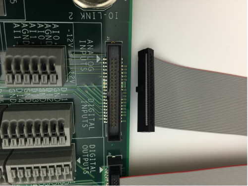 Figure 8. Pocket IO Connected to MAXREFDES150ATACH#.
Finally, take the 24V wall adapter and select the correct fixture for the local power outlet; the kit is supplied with adapters for England, Europe, USA and Australia standards (Figure 9).
 Figure 9. Pocket IO power supply and adapters.
Connect the 24V supply to the barrel connector on the plastic case (Figure 10).
 Figure 10. Pocket IO with Power Supply Connected.
Pocket IO is now ready to be powered on and tested. Testing requires a PC loaded with Arduino software for Pocket IO.
Procedure
Maxim Pocket IO Arduino Installation Instructions
- Download and install the latest Arduino IDE.
a. Go to https://www.arduino.cc/en/Main/Software.
b. Select the appropriate OS link (Windows, MAC®, Linux®). For this Quick Start we assume the OS is Windows PC.

c. Follow the prompts to download and save the file.

- Install the latest Arduino IDE.
a. Once the download has completed double click 'Arduino-x.x.xx-windows.exe.'
b. Windows then prompts you to run this file, select 'Run.'
c. The Arduino setup displays the license agreement, select 'I Agree.'

d. It prompts you to select components to install, select 'Next.'

e. Next it shows the destination folder to install, select 'Install.'

f. When Arduino setup is completed select 'Close.'

- Install Maxim's Pocket IO Board.
a. Locate the 'Arduino' shortcut on your desktop and double click the icon to open the Arduino IDE.
b. A window opens as shown below, select File > Preferences.

c. In the 'Preferences' window there is a section 'Additional Boards Manager URLs.' Select this box.

d. In the box that opens, copy and paste the URL below into this window and select 'OK', then 'OK' again. https://raw.githubusercontent.com/maximTicer/pocketio/master/package_maxim_index.json

e. Select Tools > Board > Board Manager.

f. Open the 'Boards Manager' window and from the drop down Type menu select 'Certified.'

g. Select 'Intel i686 Boards by Intel' for Edison and click 'Install' to install rev 1.6.7+1.0 or later.

h. Once installation is completed, select 'Close.'

i. Open the 'Boards Manager' window and from the drop down Type menu select 'Contributed.'

j. Select 'Maxim Boards by Maxim Integrated' for Pocket IO and click 'Install.'

k. Once installation is completed, select 'Close.'

- Using the Pocket IO with Arduino IDE.
a. To select Pocket IO as the target board, select Tools > Board > Maxim Pocket IO.

b. Make sure Pocket IO is powered with 24V, and connect the USB cable to the micro-USB connector labeled 'Edison Status' (the one nearest to the green connector). If device drivers are not automatically installed use this link to download and install the drivers: http://downloadmirror.intel.com/24909/eng/IntelEdisonDriverSetup1.2.1.exe
c. Select Tools > Port > COMXXX (where xxx is whichever COM port was selected when you plugged it in).

d. Next select File > Examples > PioDo > PioDoBlink.

e. A new window should appear with the example sketch selected. Press the circular button with the check mark in the top left corner to 'Verify' or compile the sketch.

f. The window indicates it is compiling with a progress bar, and when finished, displays 'Done Compiling.'

g. Now select the circular button with the right arrow, 'Upload' transfers the data to the Edison and starts to run the compiled program.

h. After a few seconds the message 'Done Uploading' is displayed and you can see the LEDs on the board flashing driven by the digital outputs.
i. A number of standard functions are included as examples to showcase the functionality of Pocket IO, or the user can develop their own sketches.
Arduino is a registered trademark of Arduino, LLC.
IEC is a registered service mark of the International Engineering Consortium, Inc.
Intel is a registered trademark and registered service mark of Intel Corporation.
IO-Link is a registered trademark of Profibus User Organization (PNO).
Linux is a registered trademark of Linus Torvalds.
Mac OS is a registered trademark of Apple Inc.
Pocket IO is a trademark of Maxim Integrated Products, Inc.
Wi-Fi is a registered certification mark of Wi-Fi Alliance Corporation.
Windows is a registered trademark and registered service mark of Microsoft Corporation.