Altera DSP Development Kit, Cyclone III Edition
详情介绍
概览
设计资源
评估硬件
产品型号带"Z"表示符合RoHS标准。评估此电路需要下列选中的电路板
- EVAL-CFTL-6V-PWRZ ($17.00) Wall Power Supply for Eval Board
- EVAL-CN0150A-SDPZ ($60.00) Software Calibrated, 1 MHz to 8 GHz, 70 dB RF Power Measurement System Using the AD8318 Logarithmic Detector
- EVAL-SDP-CB1Z ($99.00) Eval Control Board SDP
驱动/参考代码
Software such as C code and/or FPGA code, used to communicate with component's digital interface.
电路功能与优势
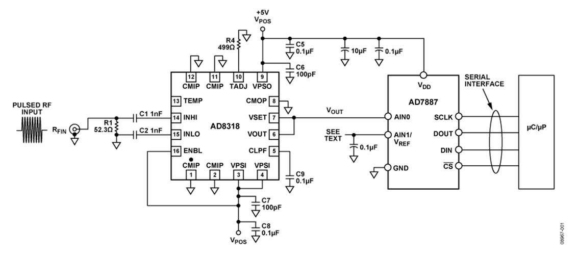
本电路用于测量1 MHz至8 GHz频率的RF功率,测量范围约为60 dB。测量结果作为数字码在一个12位ADC的输出端提供,该ADC配有串行接口和集成基准电压源。RF检波器的输出端可与ADC实现无缝接口,并使用ADC的大部分输入范围,而无需进一步调整。在数字域执行简单的2点系统校准。
对于1 MHz至6 GHz信号,AD8318 能保持精确的对数一致性,并能在最高8 GHz下工作。典型输入范围为60 dB (re: 50 Ω),误差小于±1 dB。AD8318的响应时间为10 ns,能够检测45 MHz以上的RF突发脉冲。在整个温度范围内,该器件具有极佳的对数截距稳定性(±0.5 dB)。
通过片内控制寄存器可将AD7887配置为单通道或双通道工作模式。在默认的单通道模式下,AD7887可作为只读ADC工作,从而简化控制逻辑。
所示数据为两个器件在−40°C至+85°C温度范围内工作的情况。

电路描述
将受测的RF信号施加于AD8318。该器件配置为所谓的“测量模式”,引脚VSET与VOUT相连。这种模式下,输出电压与输入信号电平呈线性dB关系(标称值为−24 mV/dB),典型输出电压范围为0.5 V至2.1 V。
AD8318的输出直接连到12位ADC AD7887。该ADC使用自己的内部基准电压源,输入范围配置为0 V至2.5 V,因此LSB大小为610 μV。当RF检波器提供标称值−24 mV/dB的斜率时,数字分辨率为39.3 LSB/dB。由于分辨率如此高,因此调整来自RF检波器的0.5 V至2.1 V信号,以便恰好符合ADC的0 V至2.5 V范围并无多大意义。
该检波器的传递函数可以近似表示为以下方程式:
![]()
其中,SLOPE 为斜率,单位mV/dB(标称值−24 mV/dB);Intercept为y轴截距,单位dBm(标称值20 dBm);PIN 为输入功率,单位dBm。图2给出了检波器输出电压与输入功率的典型关系图。

在ADC的输出端,该方程式可以表示为:
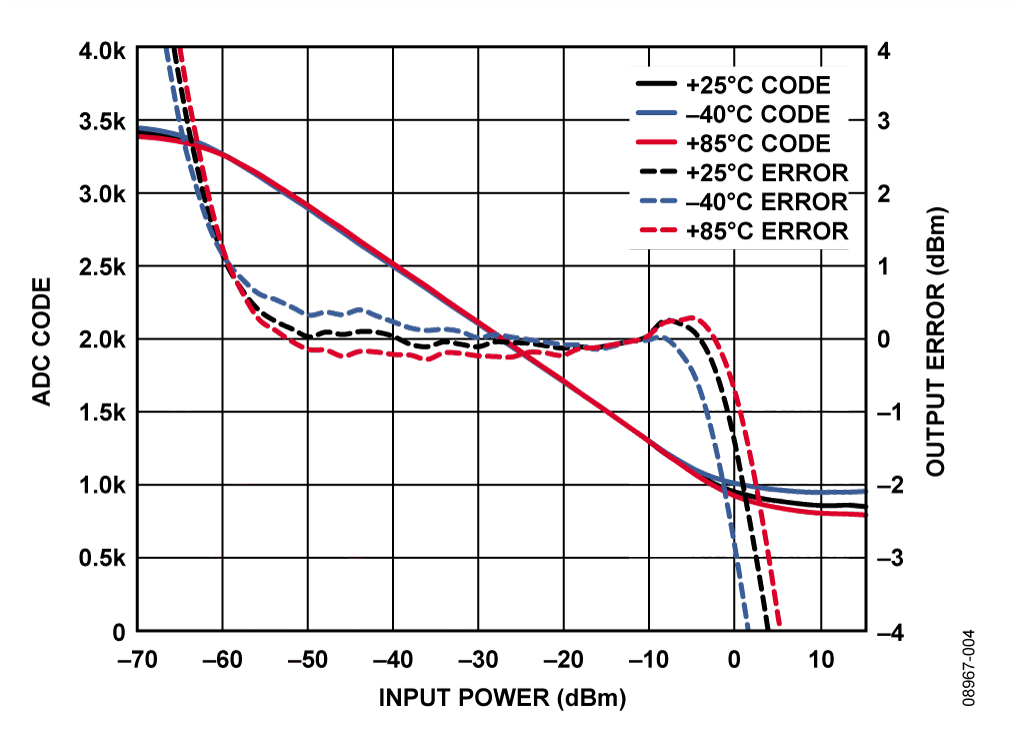
其中,SLOPE_ADC为码数/dBm,PIN 和Intercept 均用dBm表示。图3以输入功率与所观察到的ADC码的关系显示典型的检波器功率扫描情况。
Because the slope and intercept of the system vary from device to device, a system level calibration is required. A calibration is performed by applying two known signal levels close to the endpoints of the AD8318 linear input range and measuring the corresponding output codes from the ADC. The calibration points chosen should be well within the linear operating range of the device (−10 dBm and −50 dBm in this case).
利用两个已知输入功率水平( PIN_1和PIN_2)及所观察到的对应ADC码( CODE_1和 CODE_2),便可以通过下式计算 SLOPE_ADC和 Intercept:
在工厂校准过程中计算并存储SLOPE_ADC和Intercept 之后(存储在非易失性RAM中),就可以利用它们通过下式计算设备在现场工作时的未知输入功率水平PIN:

Figure 3 through Figure 8 show how the system transfer function deviates from this straight line equation, particularly at the endpoints of the transfer function. This deviation is expressed in dB using the equation

其中,CODE_OUT为ADC输出码;SLOPE_ADC 为所存储的ADC斜率,单位为码数/dBm;Intercept为所存储的斜率;PIN_TRUE为实际输入功率。
图3至图8显示一个RF功率测量系统使用AD8318和AD7887BR所能获得的系统性能。图中曲线反映的是RF输入功率(dBm)与ADC输出码和输出误差(dBm)的关系。生成这些曲线所用的数据是在各种输入功率电平、频率、温度以及使用ADC内部或外部基准电压源下测得的。从这些图还可以看出:当ADC使用低漂移外部基准电压源时,可以提高系统性能并降低温度所引起的漂移。关于使用外部基准电压源的更多详细信息,请参阅“常见变化”部分。
A complete design support package for this circuit note can be found at www.analog.com/CN0150-DesignSupport.


常见变化
AD7887是一款双通道、12位ADC,配有SPI接口。如果最终应用只需一个通道,则可以使用12位AD7495。在需要多个ADC和DAC通道的多通道应用中,可以使用AD7294。除提供四路12位DAC输出外,这款子系统芯片还含有4个非专用ADC通道、2路高端电流检测输入和3个温度传感器。电流和温度测量结果经过数字转换后,可通过I2C兼容接口读取。
利用外部ADC基准电压源可以改善该电路的温度稳定性。AD7887的2.5 V内置基准电压源具有50 ppm/°C漂移,在125°C温度范围内漂移约15 mV。检波器的斜率为−24 mV/dB,因此该ADC基准电压漂移将为预期温度漂移误差贡献大约±0.3 dB。在类似的温度范围内,AD8318的温度漂移约为±0.5 dB(具体取决于频率,详情参见AD8318数据手册)。
如果使用外部基准电压源,建议考虑2.5 V基准电压源ADR421 。它的温度漂移为1 ppm/°C;在−40°C至+85°C范围内,基准电压变化只有312 μV,这对系统整体温度稳定性的影响可以忽略不计。.
如果动态范围要求较低,可以使用 AD8317 (55 dB) 或 AD8319 (45 dB) 对数检波器。
电路评估与测试
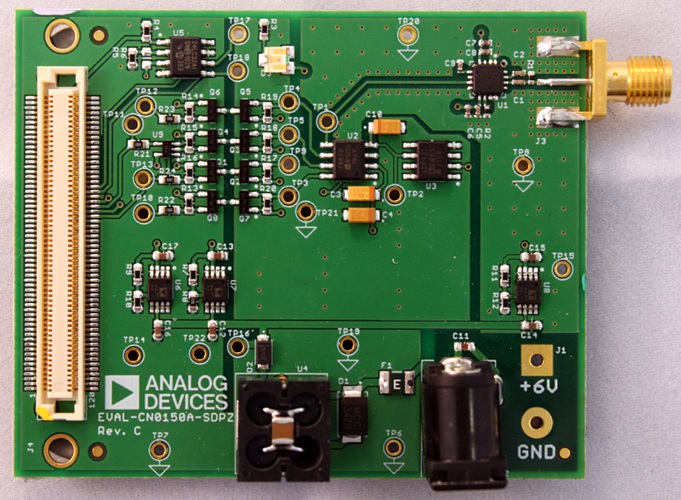
This circuit uses the EVAL-CN0150A-SDPZ circuit board and the EVAL-SDP-CB1Z System Demonstration Platform (SDP) evaluation board. The two boards have 120-pin mating connectors, allowing for the quick setup and evaluation of the circuit’s performance. The EVAL-CN0150A-SDPZ board contains the circuit to be evaluated, as described in this note, and the SDP evaluation board is used with the CN0150A evaluation software to capture the data from the EVAL-CN0150A-SDPZ circuit board.
Equipment Needed
- PC with a USB port and Windows® XP or Windows Vista® (32-bit), or Windows® 7 (32-bit)
- EVAL-CN0150A-SDPZ Circuit Evaluation Board
- EVAL-SDP-CB1Z SDP Evaluation Board
- CN0150A Evaluation Software
- Power supply: +6 V, or +6 V “wall wart”
- Environmental chamber
- RF signal source
- Coaxial RF cable with SMA connectors
Load the evaluation software by placing the CN0150A Evaluation Software disc in the CD drive of the PC. Using "My Computer," locate the drive that contains the evaluation software disc and open the Readme file. Follow the instructions contained in the Readme file for installing and using the evaluation software.
Functional Block Diagram
See Figure 1 of this circuit note for the circuit block diagram and the file “EVAL-CN150A-SDPZ-SCH-Rev0.pdf” for the circuit schematics. This file is contained in the CN0150 Design Support Package.
Setup
Connect the 120-pin connector on the EVAL-CN0150A-SDPZ circuit board to the connector marked “CON A” on the EVAL-SDP-CB1Z evaluation (SDP) board. Nylon hardware should be used to firmly secure the two boards, using the holes provided at the ends of the 120-pin connectors. Using an appropriate RF cable, connect the RF signal source to the EVAL-CN150A-SDPZ board via the SMA RF input connector. With power to the supply off, connect a +6 V power supply to the pins marked “+6V” and “GND” on the board. If available, a +6 V "wall wart" can be connected to the barrel connector on the board and used in place of the +6 V power supply. Connect the USB cable supplied with the SDP board to the USB port on the PC. Note: Do not connect the USB cable to the mini USB connector on the SDP board at this time.
Test
Apply power to the +6 V supply (or “wall wart”) connected to EVAL-CN150A-SDPZ circuit board. Launch the evaluation software, and connect the USB cable from the PC to the USB mini connector on the SDP board.
Once USB communications are established, the SDP board can now be used to send, receive, and capture serial data from the EVAL-CN150A-SDPZ board.
Temperature testing was performed using a Test Equity Model 107 environmental chamber. The EVAL-CN150A-SDPZ evaluation board was placed in the chamber via a slot in the test chamber door, with the SDP evaluation board extending outside.
Information and details regarding how to use the evaluation software for data capture can be found in the CN0150A evaluation software Readme file.
Information regarding the SDP board can be found in the SDP User Guide.
讨论
- 加入我的myAnalog 登录 myAnalog


