DE10-Nano 套件
详情介绍
概览
设计资源
评估硬件
产品型号带"Z"表示符合RoHS标准。评估此电路需要下列选中的电路板
- AD8331-EVALZ ($82.38) AD8331 evaluation board used to evaluate this circuit. Please see "Circuit Evaluation & Test" section for set up information.
优势和特点
- 将10位65MSPS ADC的动态范围扩展至高于100dB
- 针对高速度进行优化
- 针对超声波接收器应用进行设计
电路功能与优势
The circuit shown in Figure 1 uses the AD8331 low noise wideband VGA as a driver to extend the dynamic range of the AD9215 10-bit ADC. The gain range of the AD8331 is 48 dB and is linear-in-dB with respect to the control voltage. The overall dynamic range of the combined VGA and ADC is greater than 100 dB.
Variable gain amplifiers (VGAs) serve a critical function when an analog signal with wide dynamic range is converted to digital format, and the ADC resolution is insufficient to capture all useful information. For example, a 10-bit converter with a 2 V p-p input range has an LSB weight of 2 ÷ 1024, or just under 2 mV.

This represents a dynamic range of approximately 60 dB. A wideband VGA can be used ahead of the ADC to amplify input signals with amplitudes less than the minimum resolution and attenuate large signals that would otherwise saturate the ADC.
Examples of such applications are ultrasound receivers where the signal strength ranges from microvolts to several volts, and the intermediate frequency (IF) amplifier used in virtually all receivers. For dc or low frequency analog signals, Σ-Δ ADCs with resolutions up to 24 bits are economical and plentiful, but typically limited in sampling frequency to a few hundred kilohertz. State-of-the-art, available ADC resolution decreases as sampling frequency increases. This makes accurate digitization of high frequency, low amplitude signals extremely difficult using standard ADCs.
AD8331/AD8332/AD8334分别是单通道/双通道/四通道、超低噪声、线性dB可变增益放大器(VGA),针对超声系统进行了优化,可以用作低噪声可变增益元件,工作频率最高达120 MHz。
各通道内置一个超低噪声前置放大器(LNA)、一个48 dB增益范围的X-AMP® VGA以及一个具有可调输出限制功能的可选增益后置放大器。LNA增益为19 dB,具有单端输入和差分输出。LNA输入阻抗可以利用一个电阻来调节,以便与信号源相匹配,且不影响噪声性能。
VGA的48 dB增益范围使这些器件适合各种不同的应用。带宽在整个增益范围内可保持出色的一致性。对于40 mV至1 V范围内的控制电压,增益控制接口可提供精确的50 dB/V线性dB调整。通过工厂调整可确保器件间及通道间具有出色的增益匹配特性。
电路描述
图1所示电路展现了典型VGA与ADC的互连情况。对于本例,AD8331 VGA与AD9215 ADC在频率范围和差分接口匹配方面兼容。为简明起见,图中未显示电源去耦。
AD8331内置一个低噪声前置放大器,后接一个差分衰减器和增益级。此VGA仅需5 V单电源供电。ADC的低噪声3 V电源可由与5 V电源相连的LDO提供,例如 ADP3339。该VGA的差分输出用于驱动具有差分输入的ADC,其输入范围为1 V峰峰值至约4.5 V峰峰值。AD9215的输入范围可以设置在1 V峰峰值差分与2 V峰峰值差分之间。对于本电路,ADC输入范围设置为2 V峰峰值差分。
与大多数单电源器件一样,AD8331需要一个电压为供电电压中间值的内部基准电压源,用于一对镜像放大器,它可在输出端(折合到共模电压CMV)提供相等但极性相反的信号。关于此功能的更多信息,请参考AD8331数据手册 。VGA的引脚11 (VCM)既可以作为输入,也可以作为输出。作为输出时,VCM电路可以在引脚11上进行去耦,或者可以通过一个电压源驱动该引脚,以修改共模电压的值,从而适应具有不同输入范围的各种ADC。如果保持浮地,VCM电压将为电源电压的一半,这对于交流耦合应用是最佳值。
引脚12 (CLMP)将输出摆幅箝位在ADC差分输入的限制内,从而避免出现可能会严重影响转换器的过驱问题。利用一个简单的电阻控制箝位幅度。如果CLMP引脚上没有任何连接,则箝位电压为以2.5 V共模电压为中心的差分4.5V峰峰值。
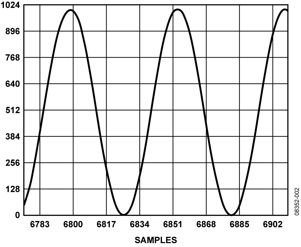
测试波形选择1 MHz正弦波,利用 ADC Analyzer™软件恢复的波形如图2所示。采样频率为65 MSPS,对应于AD9215的65 MSPS版本。LNA输入信号为70 mV峰峰值,经过外部低通和高通滤波器处理,可滤除信号发生器的杂散。VGA增益为29 dB,可将信号放大到大约ADC满量程输入电压的一半。VGA与ADC之间的高通和低通滤波组合可衰减50 kHz以下的低频噪声(33 Ω和100 nF可产生48 kHz的低频截止频率),以及100 MHz以上的频率(42 pF和33 Ω可产生114 MHz的高频截止频率)。
LNA输入信号为70 mV峰峰值, 经过外部低通和高通滤波器处理,可滤除信号发生器的杂散。VGA增益为29 dB,可将信号放大到大约ADC满量程输入电压的一半。VGA与ADC之间的高通和低通滤波组合可衰减50 kHz以下的低频噪声(33 Ω和100 nF可产生48 kHz的低频截止频率),以及100 MHz以上的频率(42 pF和33 Ω可产生114 MHz的高频截止频率)。
通过减小LNA输入端以及LNA与VGA输入端之间的串联电容值,可以进一步实现高通滤波。

如果VOH和VOL上的PCB走线杂散电容约超过25 pF,则可能需要一个输出去耦网络,它由100 Ω固定电阻与 AD8331各输出端串联插入的一个铁氧体磁珠并联组成。否则,便不需要这一网络。
大部分现代ADC都可以通过引脚接入内部基准电压源。AD9215的内部基准电压为1 V,外部电阻使共模输入电压偏置3 V电源电压的一半。
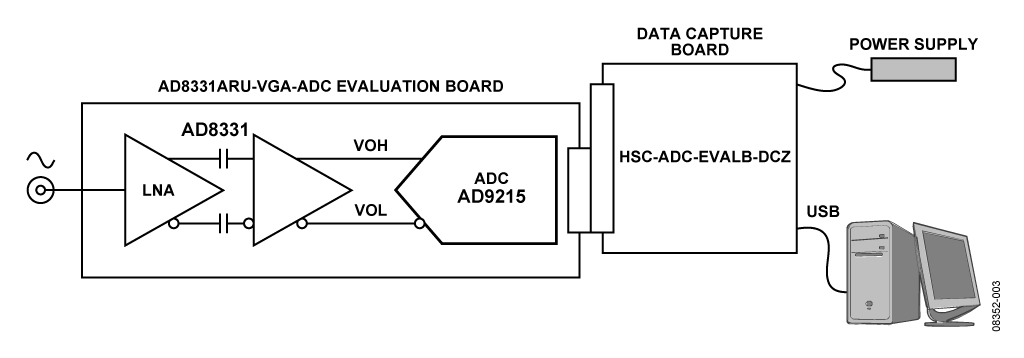
数据捕捉板与笔记本电脑接口。ADC Analyzer软件可启动转换器,并提供波形或FFT显示。关于AD9215配置的详细信息,请参考AD9215数据手册。
图3是该测试设置的简化框图。评估板上装有一个20引脚、双排接头,它与转换器接口板上的连接器一半相结合。评估板由标准笔记本电脑上运行的ADC Analyzer软件进行控制。
本电路必须构建在具有较大面积接地层的多层电路板上。为实现最佳性能,必须采用适当的布局、接地和去耦技术(请参考 教程MT-031——“实现数据转换器的接地并解开AGND和DGND的谜团”,以及 教程MT-101——“去耦技术”)。
A complete design support package for this circuit note can be found at http://www.analog.com/CN0096-DesignSupport.

电路评估与测试
Equipment Needed
Windows® XP, Windows Vista (32-bit), or Windows 7 (32-bit) PC with USB port, AD8331ARU-VGA-ADC, HSC-ADC-EVALB-DCZ evaluation boards, and the AD9215 evaluation software, power supplies, spectrum analyzer, signal source. See user guide UG-173 and the AD8331 and AD9215 data sheets for additional details.
Getting Started
See user guide UG-173 for the HSC-ADC-EVALB-DCZ data capture evaluation board operation and installation of the ADC Analyzer software. See Figure 1 of this circuit note for the block diagram, "AD8331ARU-VGA-ADC-SCH-Rev0.pdf” for schematics, AD8331ARU-VGA-ADC-AssemblyDrawing-RevA.pdf, and the “AD8331ARU-VGA-ADC-BOM-Rev0.pdf” for the bill of materials.
Functional Block Diagram
See user guide UG-173 and Figure 1 of this circuit note for the circuit block diagram. Also see file “AD8331ARU-VGA-ADC-SCH-Rev0.pdf” for the schematics.
Setup and Test
See Circuit Description section for setup and test details and user guide UG-173 for the HSC-ADC-EVALB-DCZ data capture evaluation board. UG-173 describes the board operation, and installation of the ADC Analyzer software. Also see Figure 1 of this circuit note for the block diagram.
讨论
- 加入我的myAnalog 登录 myAnalog


