Medical Imaging
详情介绍
Designing MRI Equipment
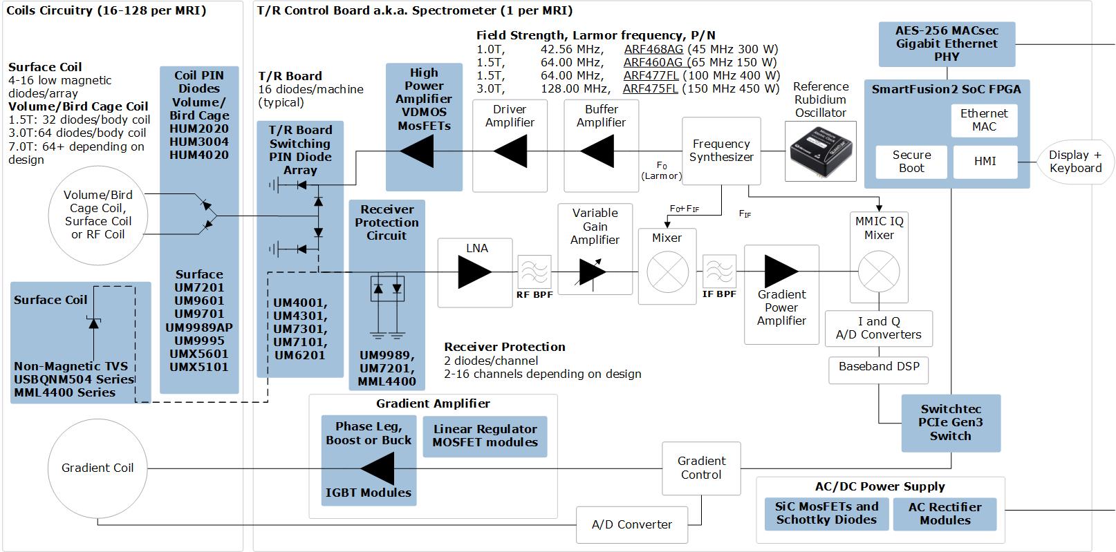
Magnetic resonance imaging (MRI) is a medical imaging technique using radio waves and magnetic fields to create detailed cross-sectional images of internal organs and structures within the body. Widely used in patient analysis and medical diagnosis, MRI often reveals different information about bodily structures than can be visualized using other imaging methods such as X-ray, computed tomography (CT) or ultrasound. Explore Microsemi's solutions for MRI equipment:
Microsemi offers key technologies and services as part of its portfolio to deliver smaller, smarter and more reliable solutions for your medical imaging applications. Our portfolio for MRI equipment designs includes:
- Rubidium Component Clocks: 50% lower power, smallest form factor and highest accuracy over temperature
- Power and RF Discretes: Including SiC Diodes/FETs, discretes and power modules , non-magnetic TVS, RF pin diodes, and RF MosFETs.
- FPGAs and SoCs: Non-volatile, SEU immune, low power, small form factor and secure
Microsemi is well-known for its high-reliability, high-performance solutions. Our medical solutions portfolio is aligned to help you deliver innovative implantable device therapies, diagnostics and monitoring solutions enabling better patient care and quality of life. Contact your local Microsemi sales office today to find the right technologies and products for your medical imaging design needs.
Component Clocks: RF Oscillators for MRI Equipment
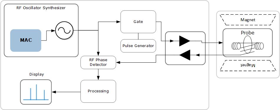
Magnetic resonance imaging (MRI) equipment requires a local reference oscillator, in order to serve as a source for all the RF components in the multiple MRI circuit boards. Microsemi's Rubidium MAC (Miniature Atomic Clock) is ideal for medical imaging applications to serve as this local reference oscillator.Rubidium MAC Advantages for MRIs
- MRIs require an accurate and a stable reference source
- Low power consumption and size help reduce the footprint
- Better accuracy reference results in less frequent calibration of the customer system
| Feature |
MAC |
Traditional Rubidium |
| Size |
Smaller |
Larger |
| Power |
5 W @ 25ºC |
~10W : ~2X MAC |
| Frequency Stability |
No hops & pops |
Hop & pops |
| TEMPCO |
Better |
Worse |
| Accuracy (10 MHz) |
<0.0005 Hz |
<0.0005 Hz |
Ready to learn more? Contact your local Microsemi sales office today to find the right technologies and products for your medical imaging design needs.
SiC Diodes/FETs for MRI Power Conversion
Silicone Carbide (SiC) Schottky Diodes and MosFETs offer superior dynamic and thermal performance over conventional silicon power diodes and MosFETs. The table below summarizes the advantages of SiC vs Si power discretes.| Characteristics |
SiC vs. Si |
Results |
Benefits |
| Breakdown Field |
10x Higher |
Lower On-Resistance |
Higher efficiency |
| Band Gap |
3x Higher |
Higher operating temperature |
Improved cooling |
| Thermal conductivity |
3x Higher |
Higher power density |
Higher current capabilities |
| Positive Temperature coefficient |
- |
Self regulation |
Easy paralleling |
| Temperature Independent switching behavior |
- |
Stable high temperature performance |
Lower losses |
| Almost no Reverse Recovery charge |
- |
Lower switching losses Higher switching capabilities |
Higher performance |
Microsemi SiC Schottky Diode Advantages
- Superior Passivation Technology: leads to higher reliability. Microsemi thin film passivation applied in the wafer fab vs. competitors’ spin on passivation applied post wafer fab.
- Patented Technology: Junction barrier structure has a lower VF than any equivalent die size (due to larger Schottky area and buried P-Wells).
Microsemi SiC MosFETs Advantages
- Best in Class RDS(on) vs Temperature: leads to lower switching losses as well as stability over the complete operating temperature range.
- Longest Short Circuit Withstand Rating: highest simple easy control circuit design
Microsemi also manufactures SiC Schottky Diode Modules and SiC MosFET Modules, which allow higher integration and lower time to market.
SiC Documentation
Ready to learn more? Contact your local Microsemi sales office today to find the right technologies and products for your medical imaging design needPower Modules
Microsemi's Power Modules products are a great fit for several MRI subsystems, including Gradient Amplifiers (phase leg IGBTs, as well as buck or boost), AC rectifier Bridges (Diode modules) and high power liner regulators (MOSFET modules). To select the best Microsemi Power Module for MRI power sub-systems, please chose from the selection tables below.Chopper & Phase Leg IGBT Modules
| VCES (V) |
IGBT type |
IC (A) Tc=80C |
VCE(on) (V) at rated IC |
Package |
NTC |
BOOST | BUCK | PHASE LEG |
| 1200 |
NPT FAST |
300 |
3.2 |
SP6 |
option |
|||
| 300 |
3.2 |
D3 |
option |
|||||
| TRENCH 4 |
90 |
1.85 |
SP1 |
YES |
||||
| 180 |
1.85 |
SP3 |
YES |
N/A |
N/A |
|||
| 325 |
1.85 |
D3 |
option |
|||||
| 475 |
1.85 |
D3 |
option |
|||||
| 700 |
1.85 |
D3 |
option |
N/A |
||||
| TRENCH 4 FAST |
100 |
2.05 |
SP3 |
YES |
N/A |
N/A |
||
| 400 |
2.05 |
SP6 |
YES |
N/A |
N/A |
IGBT Module Technology Selection
| Technology | Module code | 600V | 650V | 1200V | Switching losses | Conduction losses | Hard switching | Soft Switching |
| NPT FAST | APTGFxxxx | 150°C | N/A | 150°C | low | Very high ~3.0V |
<50kHz | <100kHz |
| NPT MOS8 | APTGRxxxx | N/A | N/A | 150°C | low | High ~2.5V |
<50kHz | <100kHz |
| TRENCH4 | APTGLxxxx | N/A | 175°C | 175°C | Medium | Moderate ~1.8V |
<40kHz | <80kHz |
| TRENCH4 FAST | APTGLQxxxx | N/A | 175°C | 175°C | Moderate | Medium ~2.0V |
<50kHz | <100kHz |
Standard Recovery Rectifier Modules
| Prefix | Circuit | VRRM | IF | Package |
| MSD = 30mm height MSDM = Low Profile SM2-1 = 22mm SM3-1 = 17mm |
|
800V 1200V 1600V 1800V |
30A to 50A | SM1 |
| 52A to 75A | SM2-1 |
|||
| 100A to 200A | SM3-1 |
|||
| MKSD | |
36A to 120A | ||
| SD1 |
||||
| MSAD | |
|||
| 165A to 200A | SD2 |
|||
| MSCD | |
Single and Dual MOSFET Modules for Linear Regulators
| VDSS(V) |
MOSFET type |
RDS(on) (mΩ) |
Shunt resistor (mR) |
Package |
NTC |
|
|
| 100 |
MOS 5 |
9 |
4.4 |
SP1 or SP3 |
YES |
||
| 200 |
18 |
10 |
YES |
||||
| 500 |
MOSFET LINEAR |
90 |
20 |
YES |
|||
| 600 |
125 |
20 |
YES |
||||
| 1000 |
MOS 4 LINEAR |
600 |
20 |
YES |
Non Magnetic TVS: Data Integrity in MRIs
Data lines are susceptible to transient surges, and TVS arrays are typically used to suppress these transient surges. In MRIs (large magnetic field) the material used to construct TVS arrays can also be affected, reducing their effectiveness. Traditional TVS Arrays use the copper alloy A194 to make leads stiffer, which is unacceptable in harsh magnetic environments. Microsemi's Non-Magnetic TVS arrays use a different alloy, with 0% iron content, and full compatibility with MRIs. In order to deal with the inherent higher flexibility of the non-magnetic alloy, compared to Iron, Microsemi's non-Magetic TVS arrays use a QFN143 package, which is 100% compatible with the traditional SOT143. In a QFN143 package, the epoxy case prevents the leads from bending. All USBQNM504xxx TVS Arrays support 500W (8/20us pulse), protecting a single line.
Non-Magnetic TVS array selection table
| Product | Marking | Max Stand off Voltage, Vwm(V) | Min Breakdown Voltage, Vbr V(BR) @1mA |
Max Clamping Voltage, Vcl(VC)@1A | Max Clamping Voltagge, Vcl(VC)@5A | Max Standby Current, Id(ID)@Vwm | Max Capacitance C(pF) @0V&1MHz | Max Temperature Coefficienct of Vbr. alphavbr (αV(BR) | Type |
| USBQNM50403E3 | N03 | 3.3 | 4.0 | 8.0 | 11 | 200 | 3 | -5 | Unidirectional |
| USBQNM50405E3 | N05 | 5.0 | 6.0 | 10.8 | 12 | 40 | 3 | 1 | Unidirectional |
| USBQNM50412E3 | N12 | 12.0 | 13.3 | 19.0 | 26 | 1 | 3 | 8 | Unidirectional |
| USBQNM50415E3 | N15 | 15.0 | 16.7 | 24.0 | 32 | 1 | 3 | 11 | Unidirectional |
| USBQNM50424E3 | N24 | 24.0 | 26.7 | 43 | 57 | 1 | 3 | 28 | Unidirectional |
| USBQNM50403CE3 | N03C | 3.3 | 4.0 | 8.0 | 11 | 200 | 3 | -5 | Bidirectional |
| USBQNM50405CE3 | N05C | 5.0 | 6.0 | 10.8 | 12 | 40 | 3 | 1 | Bidirectional |
| USBQNM50412CE3 | N12C | 12.0 | 13.3 | 19.0 | 26 | 1 | 3 | 8 | Bidirectional |
| USBQNM50415CE3 | N15C | 15.0 | 16.7 | 24.0 | 32 | 1 | 3 | 11 | Bidirectional |
| USBQNM50424CE3 | N24C | 24.0 | 26.7 | 43 | 57 | 1 | 3 | 28 | Bidirectional |
All USBQNM504xxx TVS Arrays support 500W (8/20us pulse), protecting a single line.
Ready to learn more? Contact your local Microsemi sales office today to find the right technologies and products for your medical imaging design needs.
RF PIN Diodes for MRI
Radio-frequency (RF) coils, known also as RF resonators and
RF probes, are essential components in a MRI system. PIN diodes are used as switching elements in MRI coil switches. Selecting the right PIN diodes for your MRI coils plays a key role in the quality of the resultant MRI images. Microsemi's leading RF PIN diode portfolio is engineered to meet your equipment design needs.
Volume/Bird Cage Coils: Switching Diodes
End ring resonant/anti-resonant Switching Diodes
| Product | MRI Usage | notes |
| HUM2020 | 1.5T: 32 diodes/body coil 3.0T:64 diodes/body coil 7.0T: 64+ depending on design For diode choice, see the MRI PIN Diodes Selection Guide |
Low Magnetic not required |
| HUM3004 | Low Magnetic not required | |
| HUM4020 | Low Magnetic not required |
Surface Coils: Receive Array PIN Diodes
Loop Array or Strip Array: 4 channels and N x 4 channels
| Product | Usage | Notes |
| UM7201 | Depends on design. 4-16 diodes/array For diode choice, see the MRI PIN Diodes Selection Guide |
Low Magnetic (for >1.5T) |
| UM9601 | Low Magnetic (for >1.5T) | |
| UM9701 | Low Magnetic (for >1.5T) | |
| UM9989AP | Low Magnetic | |
| UM9995 | Low Magnetic | |
| UMX5601 | Ultra Low Magnetic | |
| UMX5101 | Ultra Low Magnetic | |
| MPS2R10-606 | SP2T Switch |
Transmit/Receive Control Boards
| Product | MRI Usage | Notes |
| UM4001 | T/R Control Circuits 16 diodes/machine (typical) For diode choice, see the MRI PIN Diodes Selection Guide |
|
| UM4301 | Low Magnetic not required | |
| UM7301 | Low Magnetic not required | |
| UM7101 | Low Magnetic not required | |
| UM6201 | Low Magnetic not required |
Receiver Protection Circuits
| Product | MRI Usage | Notes |
| UM9989 | RF Receive circuits (not in 'Bore") 2 diodes/channel 2-16 channels depending on design For diode choice, see the MRI PIN Diodes Selection Guide |
Low Magnetic not required |
| UM7201 | Low Magnetic not required |
MRI RF PIN Diodes Application Notes
RF MosFETs for Magnetic Resonance Imaging
In MRIs, the Larmor Frequency determines the choice of the RF MosFET used in the RF amplifier, according to the MRI field strength.
MRI RF Amplifier MosFET Selection Table
| MRI Field Strength | Larmor frequency of the 1H molecule | P/N | Freq Max | Output Power | Package | Pinout |
| 1.0T | 42.56MHz | ARF468AG | 45MHz | 300W | TO-264 | Main |
| ARF468B/G | 45Mhz | 300W | Alternate | |||
| 1.5T | 64.00MHz | ARF460AG |
65MHz | 150W | TO-247 | Main |
| ARF460BG | 150W | Alternate | ||||
| ARF477FL | 100Mhz | 400W | Custom 8-pin 1.5x0.57 |
|||
| 3.0T | 128.00MHz | ARF475FL | 150Mhz | 450W | Custom 8-pin 1.5x0.57 |
Main |
| ARF476FL | 150Mhz | 450W | Alternate | |||
| ARF479 |
MRI RF RF Amplifier MosFET Application Notes
-
ARF475FL, 128 MHz Pulse Amplifier in a 3T MRI application
Ready to learn more? Contact your local Microsemi sales office today to find the right technologies and products for your medical imaging design needs.
FPGAs in Medical Imaging
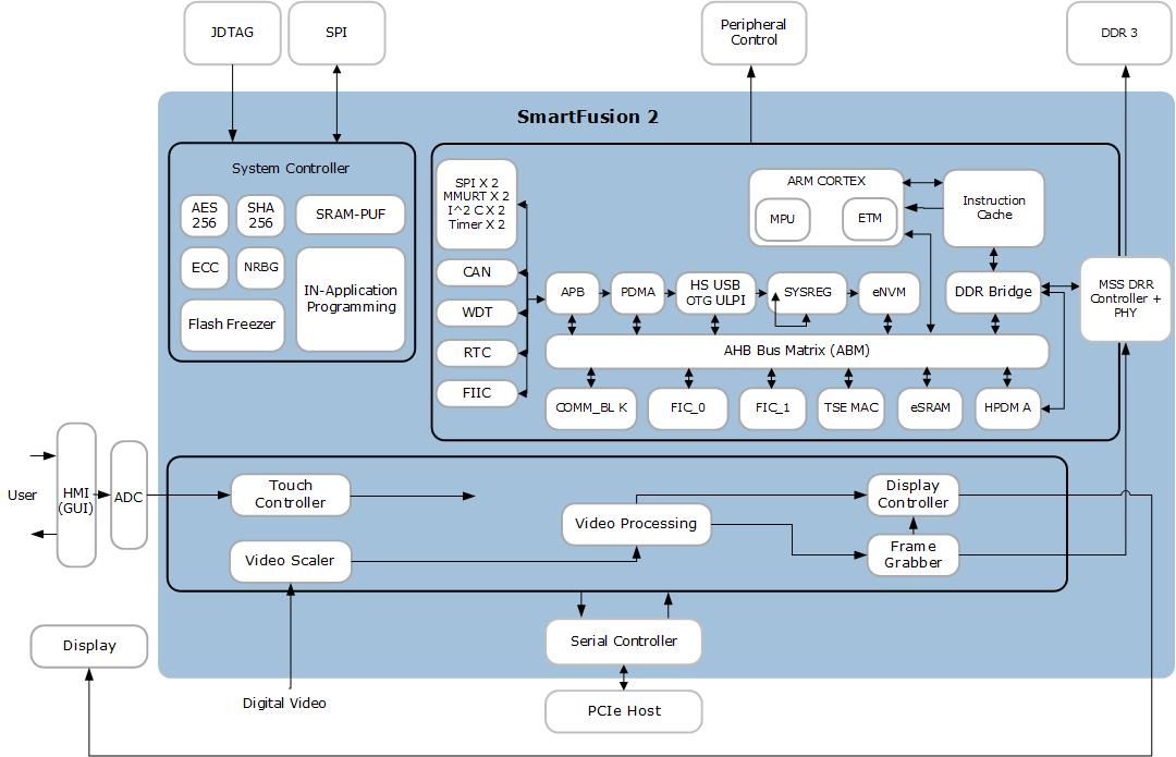
FPGAs find their usage across most of the medical imaging functions in a wide range of medical equipment’s such as CT Scans, MRIs, 3D Ultrasounds and X-Ray machines. Microsemi’s SoCs and FPGAs with their unique differentiating factors provide an ideal solution for medical applications such as Human Machine Interface (HMI), displays, frame grabbing, video capture and Image processing.
Microsemi FPGA Differentiating Factors in Medical Imaging
- Reliability with Non-Volatile Memory
- Safety/security heritage
- Low power, instant-on
- Long life cycles
- No external configuration device required
FPGA Medical Imaging Functions
- Human Machine Interface (HMI)
- Display control
- Video capture / Frame grabbing
- Thermal infrared imaging
- System control
- Analytics
For more information on FPGA based Imaging/Video solutions visit Imaging/Video
Medical Imaging FPGA Application Briefs
Solectrix SXoM-SF2 is a high performance, low power, secure and ultra-compact DSP SOM solution based on SmartFusion2 SoC FPGA devices is ideally suited for medical imaging application due to its DSP and high-speed PCIe streaming.
Ready to learn more? Contact your local Microsemi sales office today to find the right technologies and products for your medical imaging design needs.
Feature
MAC
Traditional Rubidium
Size
Smaller
Larger
Power
5 W @ 25ºC
~10W : ~2X MAC
Frequency Stability
No hops & pops
Hop & pops
TEMPCO
Better
Worse
Accuracy (10 MHz)
<0.0005 Hz
<0.0005 Hz
Characteristics
SiC vs. Si
Results
Benefits
Breakdown Field
10x Higher
Lower On-Resistance
Higher efficiency
Band Gap
3x Higher
Higher operating temperature
Improved cooling
Thermal conductivity
3x Higher
Higher power density
Higher current capabilities
Positive Temperature coefficient
-
Self regulation
Easy paralleling
Temperature Independent switching behavior
-
Stable high temperature performance
Lower losses
Almost no Reverse Recovery charge
-
Lower switching losses
Higher switching capabilities
Higher performance
VCES (V)
IGBT type
IC (A) Tc=80C
VCE(on) (V) at rated IC
Package
NTC
BOOST BUCK PHASE LEG1200
NPT FAST
300
3.2
SP6
option
300
3.2
D3
option
TRENCH 4
90
1.85
SP1
YES
180
1.85
SP3
YES
N/A
N/A
325
1.85
D3
option
475
1.85
D3
option
700
1.85
D3
option
N/A
TRENCH 4 FAST
100
2.05
SP3
YES
N/A
N/A
400
2.05
SP6
YES
N/A
N/A
Technology Module code 600V 650V 1200V Switching losses Conduction losses Hard switching Soft Switching NPT FAST APTGFxxxx 150°C N/A 150°C low Very high~3.0V <50kHz <100kHz NPT MOS8 APTGRxxxx N/A N/A 150°C low High
~2.5V <50kHz <100kHz TRENCH4 APTGLxxxx N/A 175°C 175°C Medium Moderate
~1.8V <40kHz <80kHz TRENCH4 FAST APTGLQxxxx N/A 175°C 175°C Moderate Medium
~2.0V <50kHz <100kHz Prefix Circuit VRRM IF Package MSD = 30mm height
MSDM = Low Profile
SM2-1 = 22mm
SM3-1 = 17mm
1200V
1600V
1800V 30A to 50A SM1
VDSS(V)
MOSFET type
RDS(on) (mΩ)
Shunt resistor (mR)
Package
NTC
100
MOS 5
9
4.4
SP1 or SP3
YES
200
18
10
YES
500
MOSFET LINEAR
90
20
YES
600
125
20
YES
1000
MOS 4 LINEAR
600
20
YES
Product Marking Max Stand off Voltage, Vwm(V) Min Breakdown Voltage, Vbr V(BR)@1mA Max Clamping Voltage, Vcl(VC)@1A Max Clamping Voltagge, Vcl(VC)@5A Max Standby Current, Id(ID)@Vwm Max Capacitance C(pF) @0V&1MHz Max Temperature Coefficienct of Vbr. alphavbr (αV(BR) Type USBQNM50403E3 N03 3.3 4.0 8.0 11 200 3 -5 Unidirectional USBQNM50405E3 N05 5.0 6.0 10.8 12 40 3 1 Unidirectional USBQNM50412E3 N12 12.0 13.3 19.0 26 1 3 8 Unidirectional USBQNM50415E3 N15 15.0 16.7 24.0 32 1 3 11 Unidirectional USBQNM50424E3 N24 24.0 26.7 43 57 1 3 28 Unidirectional USBQNM50403CE3 N03C 3.3 4.0 8.0 11 200 3 -5 Bidirectional USBQNM50405CE3 N05C 5.0 6.0 10.8 12 40 3 1 Bidirectional USBQNM50412CE3 N12C 12.0 13.3 19.0 26 1 3 8 Bidirectional USBQNM50415CE3 N15C 15.0 16.7 24.0 32 1 3 11 Bidirectional USBQNM50424CE3 N24C 24.0 26.7 43 57 1 3 28 Bidirectional Product MRI Usage notes HUM2020 1.5T: 32 diodes/body coil
3.0T:64 diodes/body coil
7.0T: 64+ depending on design
For diode choice, see the MRI PIN Diodes Selection Guide Low Magnetic not required HUM3004 Low Magnetic not required HUM4020 Low Magnetic not required Product Usage Notes UM7201 Depends on design.
4-16 diodes/array
For diode choice, see the MRI PIN Diodes Selection Guide Low Magnetic (for >1.5T) UM9601 Low Magnetic (for >1.5T) UM9701 Low Magnetic (for >1.5T) UM9989AP Low Magnetic UM9995 Low Magnetic UMX5601 Ultra Low Magnetic UMX5101 Ultra Low Magnetic MPS2R10-606 SP2T Switch Product MRI Usage Notes UM4001 T/R Control Circuits
16 diodes/machine (typical)
For diode choice, see the MRI PIN Diodes Selection Guide
UM4301 Low Magnetic not required UM7301 Low Magnetic not required UM7101 Low Magnetic not required UM6201 Low Magnetic not required Product MRI Usage Notes UM9989 RF Receive circuits (not in 'Bore")
2 diodes/channel
2-16 channels depending on design
For diode choice, see the MRI PIN Diodes Selection Guide Low Magnetic not required UM7201 Low Magnetic not required MRI Field Strength Larmor frequency of the 1H molecule P/N Freq Max Output Power Package Pinout 1.0T 42.56MHz ARF468AG 45MHz 300W TO-264 Main ARF468B/G 45Mhz 300W Alternate 1.5T 64.00MHz ARF460AG
65MHz 150W TO-247 Main ARF460BG 150W Alternate ARF477FL 100Mhz 400W Custom
8-pin 1.5x0.57 3.0T 128.00MHz ARF475FL 150Mhz 450W Custom
8-pin 1.5x0.57 Main ARF476FL 150Mhz 450W Alternate ARF479


